
1. Introduction
The HS-S83-PL is a 1.8 inch TFT color screen equipped with an ST7735S driver chip, with a resolution of 152 (H) × 296 (V) pixels, supporting 65K/262K color display, using a 4-line SPI communication interface, which can be quickly connected to a development board through the onboard PH2.0-8P connector, supporting 3.3V~5V wide voltage power supply, compatible with Arduino, STM32 and other mainstream platforms, with backlight control and hardware reset functions, small size, low power consumption, widely used in maker DIY, small instruments, smart toys and IoT terminal scenarios, and can realize data visualization, status display and simple interactive interface.
2. Schematic
HS-S83-PL 1.8-inch TFT Color Screen Click to view
Module Parameters
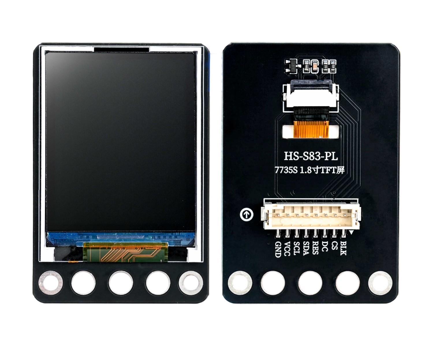
Pin Name | description |
|---|---|
GND | GND (Negative Power Input) |
VCC | VCC (Positive Power Input) |
SCL | SPI clock |
SDA | SPI data |
RES | Hardware reset |
DC | Data / command select |
CS | Select Chip |
BLK | Backlight Control |
Power Supply Voltage: 3.3V / 5V
Connection method: PH2.0 terminal wire
Installation method: Screw fixed
4, Circuit Board Size

5 of Arduino IDE example program
Attention: If prompted with an error message about the library file during program upload, please import the library file first!
Arduino IDE Library Download and Import Tutorial:Click to view
Example program (UNO development board):
#include <Adafruit_GFX.h>
#include <Adafruit_ST7735.h>
#include <SPI.h>

Adafruit_ST7735 tft = Adafruit_ST7735(A3, 9, 11, 13, 12);
/*
------------------------------------------------------------------------------------------------
|  0 0 0         0 0 0 0                     0 0 0   0 0 0 0                                   |
|  0 0 0         0 0 0 0                     0 0 0   0 0 0 0                                   |
|  0 0 0         0 0 0 0                     0 0 0   0 0 0 0                                   |
|  0 0 0         0 0 0 0       0 0 0 0 0     0 0 0   0 0 0 0     0 0 0 0 0 0                   |
|  0 0 0         0 0 0 0     0 0 0   0 0 0   0 0 0   0 0 0 0   0 0 0     0 0 0                 |
|  0 0 0 0 0 0 0 0 0 0 0   0 0 0     0 0 0   0 0 0   0 0 0 0 0 0 0 0       0 0 0               |
|  0 0 0         0 0 0 0   0 0 0       0 0 0 0 0 0   0 0 0 0 0 0 0         0 0 0               |
|  0 0 0         0 0 0 0   0 0 0 0 0 0 0 0 0 0 0 0   0 0 0 0 0 0 0         0 0 0               |
|  0 0 0         0 0 0 0   0 0 0             0 0 0   0 0 0 0 0 0 0         0 0 0               |
|  0 0 0         0 0 0 0   0 0 0             0 0 0   0 0 0 0 0 0 0 0       0 0 0               |
|  0 0 0         0 0 0 0   0 0 0 0     0 0   0 0 0   0 0 0 0   0 0 0     0 0 0                 |
|  0 0 0         0 0 0 0     0 0 0 0 0 0     0 0 0   0 0 0 0     0 0 0 0 0 0                   |
|                                                                                              |
|                                                                                              |
|                                                                                              |
|                                                                                              |
------------------------------------------------------------------------------------------------
*/
//字体:华文黑体  字号:16px  显示文字:Hello
static const unsigned char PROGMEM oled_st7735_STHeiti_16px_u0048_u0065_u006c_u006c_u006f_u0020[96]={0x70,0xF0,0x03,0xBC,0x00,0x00,0x70,0xF0,0x03,0xBC,0x00,0x00,0x70,0xF0,0x03,
0xBC,0x00,0x00,0x70,0xF1,0xF3,0xBC,0xFC,0x00,0x70,0xF3,0xBB,0xBD,0xCE,0x00,
0x7F,0xF7,0x3B,0xBF,0xC7,0x00,0x70,0xF7,0x1F,0xBF,0x87,0x00,0x70,0xF7,0xFF,
0xBF,0x87,0x00,0x70,0xF7,0x03,0xBF,0x87,0x00,0x70,0xF7,0x03,0xBF,0xC7,0x00,
0x70,0xF7,0x9B,0xBD,0xCE,0x00,0x70,0xF3,0xF3,0xBC,0xFC,0x00,0x00,0x00,0x00,
0x00,0x00,0x00,0x00,0x00,0x00,0x00,0x00,0x00,0x00,0x00,0x00,0x00,0x00,0x00,
0x00,0x00,0x00,0x00,0x00,0x00};

void setup(){
  tft.initR(INITR_BLACKTAB);
  tft.fillScreen(0xFE7F);
}

void loop(){
  //绘制位图 字体:华文黑体  字号:16px  显示文字:Hello   X坐标:0  Y坐标:8  位图宽度:48  位图高度:16
  tft.drawBitmap(0, 8, oled_st7735_STHeiti_16px_u0048_u0065_u006c_u006c_u006f_u0020, 48, 16, 0x37FF);

}
6, ESP32 Python Example (for Mixly IDE/Misashi)
Choose the development board Python ESP32 [ESP32 Generic(4MB)] and upload in code mode
Attention: If prompted with an error message about the library file during program upload, please import the library file first!
Download and import tutorial for Mixly IDE ESP32 library:Click to view
Example program (ESP32-Python):Pending update...
7, Mixly example program (graphical language)
Example program:Click to download
Attention: If prompted with an error message about the library file during program upload, please import the library file first!
Download and import tutorial of Mixly IDE Arduino library:Click to view

Example Program (ESP32 Development Board):Click to download
Attention: If prompted with an error message about the library file during program upload, please import the library file first!
Download and import tutorial for Mixly IDE ESP32 library:Click to view
Image pending update...
8. Setting up the Test Environment
Arduino UNO Test Environment Setup
Prepare Components:
HELLO STEM UNO R3 DEVELOPMENT BOARD *1
UNO-EXP4 Expansion Board*1
USB TYPE-C DATA CABLE *1
Passive buzzer module (HS-F08P) *1
1.8 inch TFT Color Screen (HS-S83-PL) *1
PH2.0-8P Connector to Dupont *1
Circuit wiring diagram:

ESP32 Test Environment Setup
Prepare Components:Pending update...
Circuit wiring diagram:Pending update...
9, Video tutorial
Video tutorial:Pending update...
10, Test results
Arduino UNO test results:
After the device is connected to the wire, burn the above program to the UNO-R3 development board, then connect the power. You will find that after the screen flickers, text or animation appears
ESP32 Test Results:
Pending update...