
1. Introduction
The EX-U+AL2(expansion board) is a配套 expansion board designed for the development board U+ PROGRAM CARD, integrating the pins of the development board on a PCB circuit board.The circuit board has both pin header interfaces and also retains the PH2.0 interface.2 types of interfaces, meeting the different wiring needs of users.Can allow users to flexibly add and remove external expansion modules.Adapter power interface: DC005/5.5-2.1MM.Supply interface input voltage range: 6-12V.Board power module output power: 5V/2A.I/O interface: 2.54 pin interface, 2.54 socket size: 65 mm*45 mm*19 mm.
2, Characteristics
1, digital IO pins (pins from D2 to D13) and analog IO (pins from A0 to A5) pins are provided. (It can meet the need of connecting extension modules with Dupont wires.)
2, There are digital IO ports PH2.0 3P sockets (pins from D2-D11) and analog IO ports PH2.0 3P sockets (pins from A0-A5) as well as 4 PH2.0 4P sockets, 2 PH2.0 5P sockets, and 1 PH2.0 6P socket.
3, There is 1 power interface for adapter power supply.
3, Expansion Board Parsing
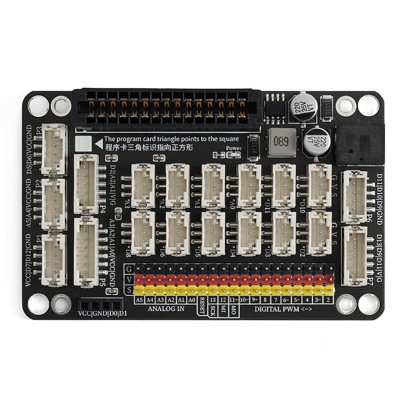
Digital IO pin (D2-D13) and Digital IO PH2.0 3P socket (D2-D11)
You can specify these IO ports as digital outputs, that is, output high level or low level.The D3 pin can be used as a hardware interrupt pin.D3, D10, D11 pins can output analog signals.
Simulation IO pin (A0-A5) and Simulation IO pin PH2.0 3P socket (A0-A3)
You can specify these IO ports for simulated input and simulated input. The simulated input returns a value of (0-1023). The simulated output value is (0-255).
Adapter power supply interface
DC005/5.5-2.1MM. Power supply interface input voltage range: 6-12V.
P1 socket
This socket circuit is designed for VCC/D7/D12/GND for convenient connection with some modules using PH2.0 4P interfaces. (Compatible module: HS-SR04L)Ultrasonic Sensor)
P2 Socket
This socket circuit is designed as A5/A4/VCC/GND for easy connection with some modules that use the PH2.0 4P interface. (Compatible module: HS-S63-LTCS342 color sensor, HS-F14LTM1650 four-digit LED digital tube module, HS-F15LTM637 four-digit clock digital tube module, HS-F19LOLED display, HS-F21LLCD1602 display, )
P3 bracket
The socket circuit is designed as D5/D6/VCC/GND for convenient connection with some modules using a PH2.0 4P interface.Voice recognition control module& HS-F04LMotor drive module& HS-F20LMotor Module, HS-F10LMotor drive module, HS-S49PLMP3 Audio Broadcast Module, HS-F23-L1-digit digital tube, HS-S60-LBluetooth module)
P4 socket
The socket circuit is designed as D2/A2/A1/VCC/GND for easy connection with some modules using a PH2.0 5P interface.Dual-axis joystick moduleHS-S32LRotary encoder)
P5 Socket
The subcircuit is designed as A3/A2/A1/A0/V/G for convenient connection with some modules using a PH2.0 6P interface.4P button module)
P6 seat
The subcircuit design is for D11/D10/D9/GND for easy connection with some modules using a PH2.0 4P interface. (Adaptable module: HS-F05LTraffic Signal Module, HS-F01LRGB LED Module)
P7 socket
This subcircuit design is for D13/D9/D11/V/G to facilitate mating with some modules using a PH2.0 5P interface. (For example, HS-F13L)8x8 dot matrix display moduleHS-F24-L1-digit digital tube)