1. Introduction
The NFC inductive read and write module is generally based on radio frequency induction principle. When an object with the corresponding identification medium (such as RFID tags, NFC tags, etc.) enters the effective induction range (the induction distance varies depending on the module type and power, from a few centimeters to several meters), it can automatically detect and identify the object, trigger subsequent data interaction operations, and is often used in automatic access control systems. When a person carries an authorized inductive card close to the card reader at a certain distance, the access control is automatically opened.
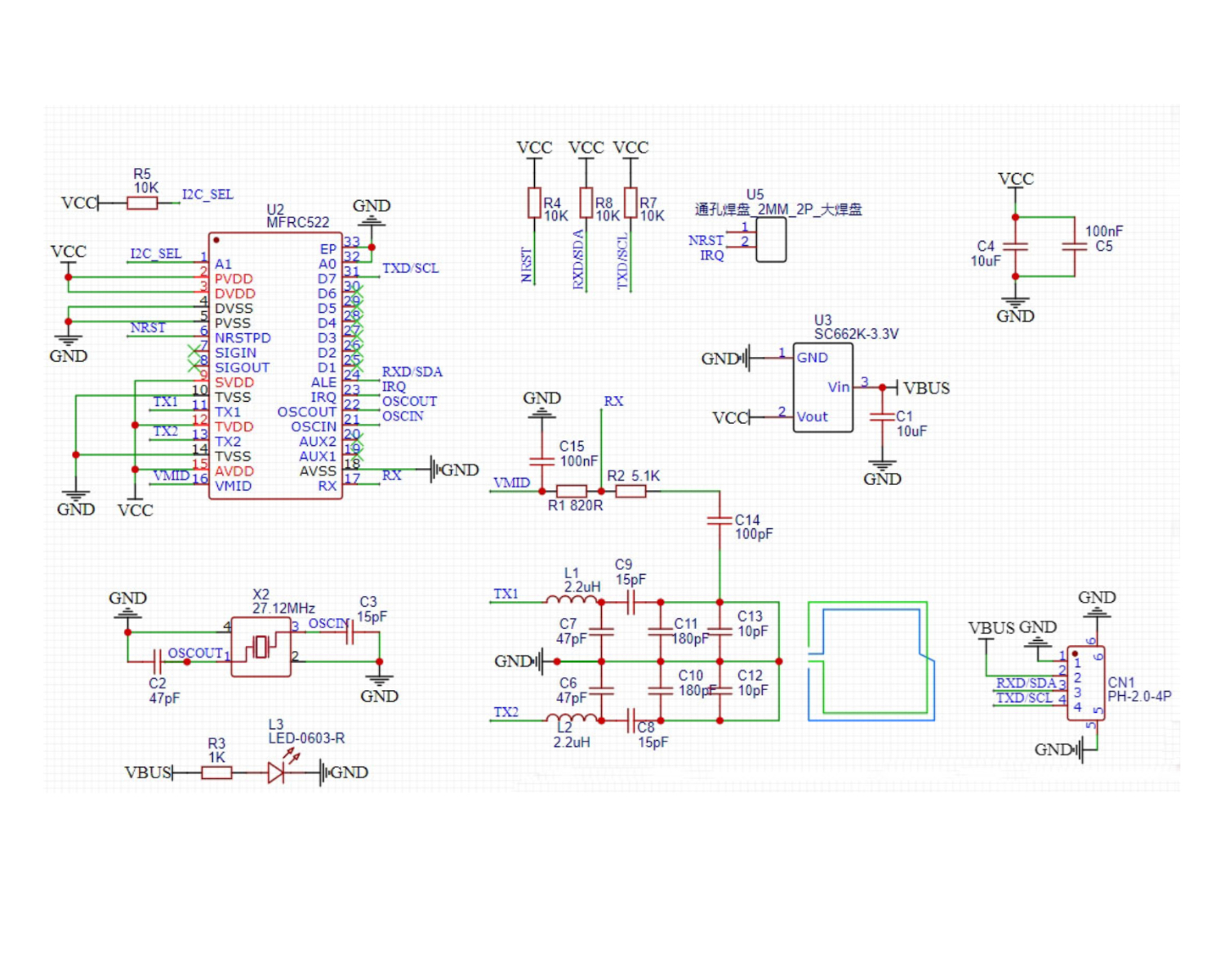
2. Schematic
Module Parameters
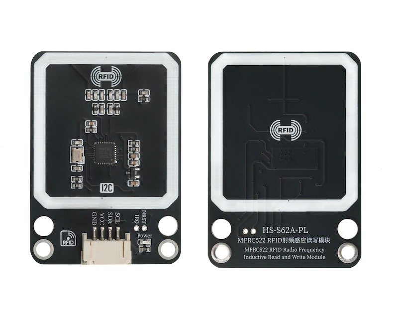
Pin Name | description |
|---|---|
G | GND (Negative Power Input) |
V | VCC (Positive Power Input) |
SDA | Data pin |
SCL | clock pin |
Supply voltage: 3.3V-5V
Connection method: PH2.0 4P terminal wire
Installation method: Modular fixed
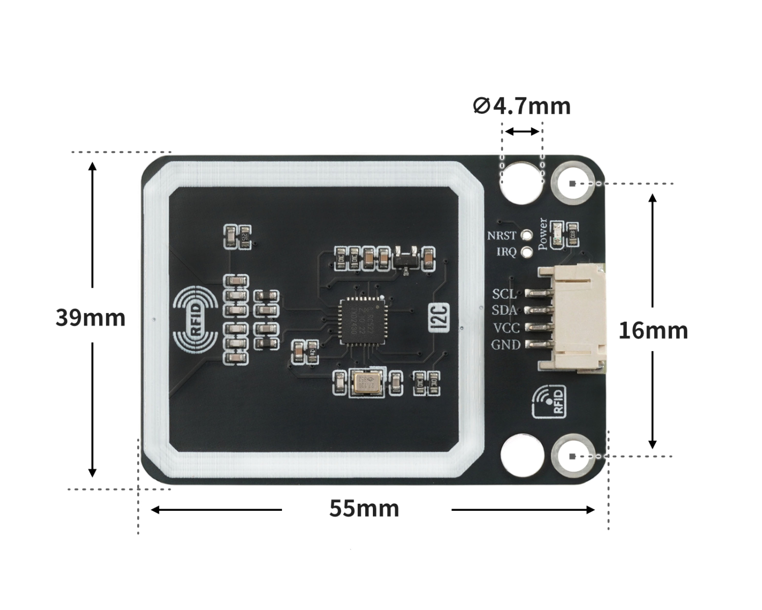
4, Circuit Board Size
Add Arduino Library File
Reference here if you don't know how to use library files:Install and use library files
Download library files: Click to download
Installation steps for the MiQi UNO development board library (download and install the MiQi library before using the code):Reference link
6, Add MicroPython environment library file
MiXin ESP32 development board library download and installation steps (download and install the MiXin library before using the code):Reference link
7. Arduino IDE example program
Example Program (UNO Development Board): Click to Download
#include "Hello_STEM_RFID.h"
#include "Wire.h"

MFRC522 mfrc522(0x28);

void setup(){
  Wire.begin();
  Serial.begin(115200);
  mfrc522.PCD_Init();
  Serial.begin(9600);
  pinMode(13, OUTPUT);
}

void loop(){
  //2133f67b
  //b6c2d896

  if ((mfrc522.PICC_IsNewCardPresent() && mfrc522.PICC_ReadCardSerial())) {
    Serial.println(String("Card UID:") + String(mfrc522.Read_Uid()));
    if (mfrc522.Read_Uid() == "2133f67b") {
      digitalWrite(13,HIGH);

    } else if (mfrc522.Read_Uid() == "b6c2d896") {
      digitalWrite(13,LOW);
    }

  }

}
Example Program (ESP32 Development Board):
8, Mixly Example Program (Graphic Language)
Example Program (UNO Development Board):Click to download
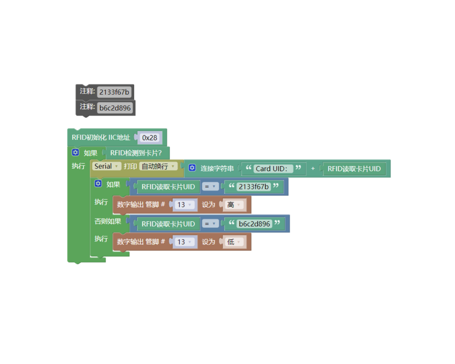
Example Program (ESP32 Development Board): Click to download
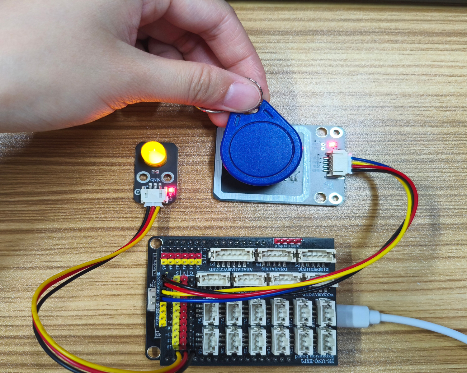
9. Setting up the Test Environment
Arduino UNO Test Environment Setup
Prepare Components:
UNO-R3 development board *1
UNO-R3 Expansion Board *1
USB TYPE-C DATA CABLE *1
HS-S62A-PL RF Inductive Read-Write Module *1
LED light module *1
PH2.0 4P Terminal Line to Dupont *1
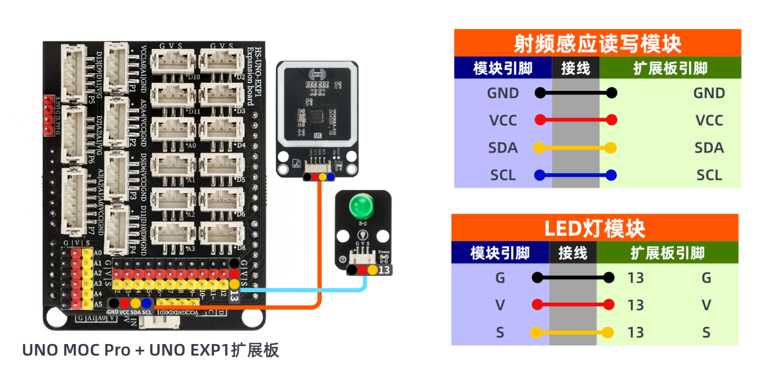
Circuit wiring diagram:
ESP32 Python test environment setup
10, video tutorial
Arduino UNO video tutorial: Click to view
ESP32 Python Video Tutorial:
11. Test Conclusion
Arduino UNO Test Conclusion:
Found serial port display bus voltage, shunt voltage, current value, power value.