1. Introduction
2. Schematic
Flame sensor HS-S07A schematicClick to view
Module Parameters
Pin Name | description |
|---|---|
G | GND (Negative Power Input) |
V | VCC (Positive Power Input) |
S | Digital Signal Pin |
A | Analog Signal Pin |
Power Supply Voltage: 3.3V / 5V
Connection Type: 2.54mm Header
Installation Method: Double Screw Fixed
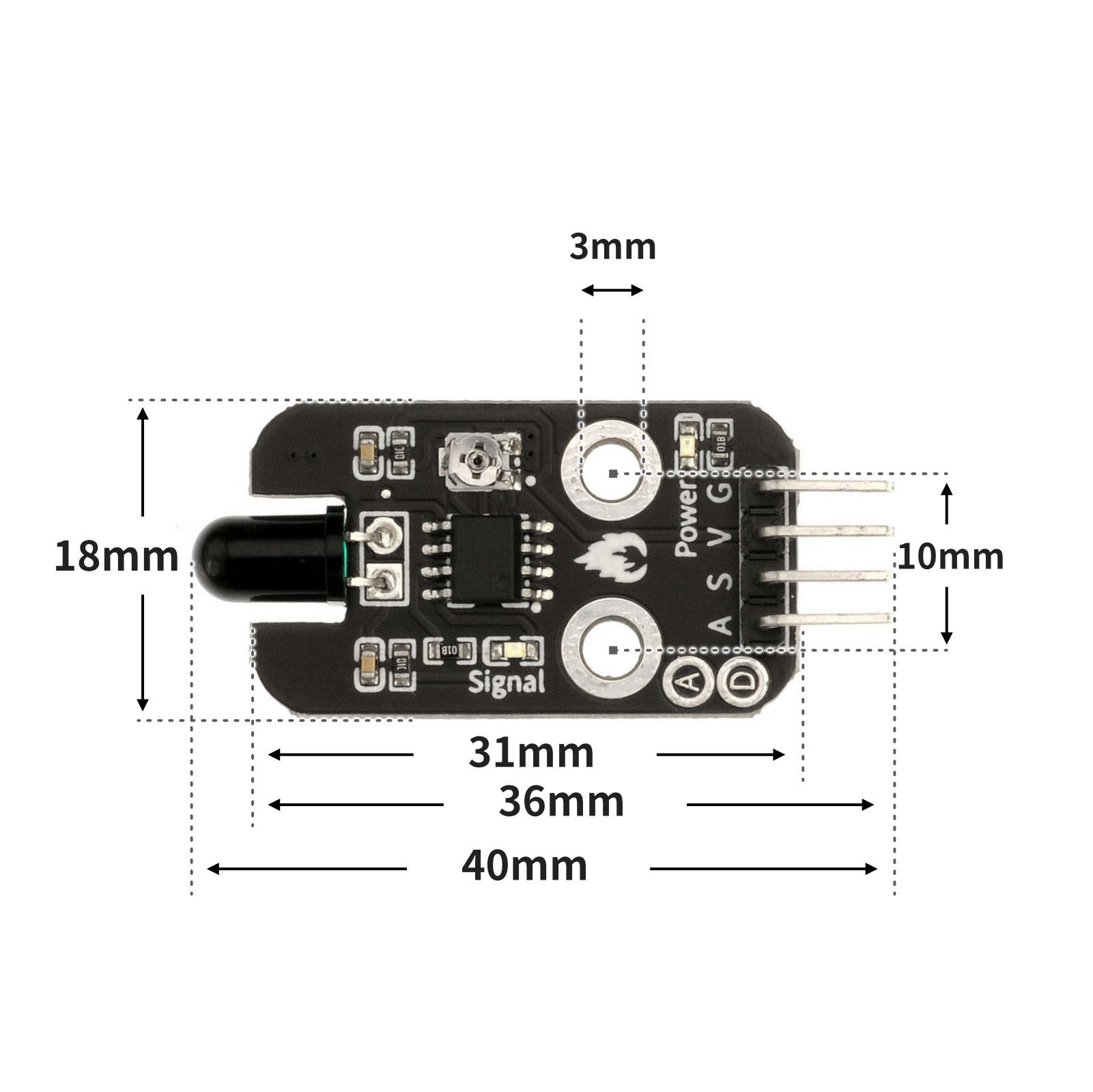
4, Circuit Board Size
5 of Arduino IDE example program
Attention: If prompted with an error message about the library file during program upload, please import the library file first!
Arduino IDE Library Download and Import Tutorial:Click to view
Example program (UNO development board):
volatile int value;

void setup(){
  Serial.begin(9600);
  value = 0;
  pinMode(4, INPUT);
  pinMode(9, OUTPUT);
}

void loop(){
  value = digitalRead(4);
  Serial.print("火焰值:");
  Serial.println(value);
  delay(1000);
  if (value == 0) {
    tone(9,196);
    delay(2000);

  } else {
    noTone(9);

  }

}
6, ESP32 Python Example (for Mixly IDE/Misashi)
Choose the development board Python ESP32 [ESP32 Generic(4MB)] and upload in code mode
Attention: If prompted with an error message about the library file during program upload, please import the library file first!
Download and import tutorial for Mixly IDE ESP32 library:Click to view
Example program (ESP32-Python):
import machine
import music


pin2 = machine.Pin(2, machine.Pin.IN)
midi = music.MIDI(4)
while True:
    if pin2.value() == 0:
        midi.pitch_time(440, 2000)
7, Mixly example program (graphical language)
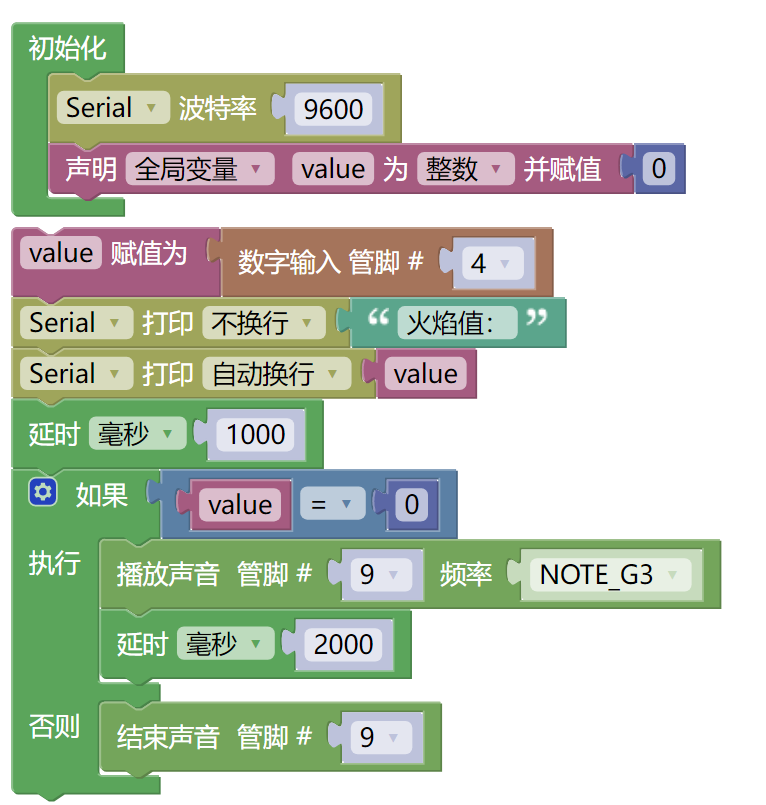
Example program (UNO development board):Click to download
Attention: If prompted with an error message about the library file during program upload, please import the library file first!
Download and import tutorial of Mixly IDE Arduino library:Click to view
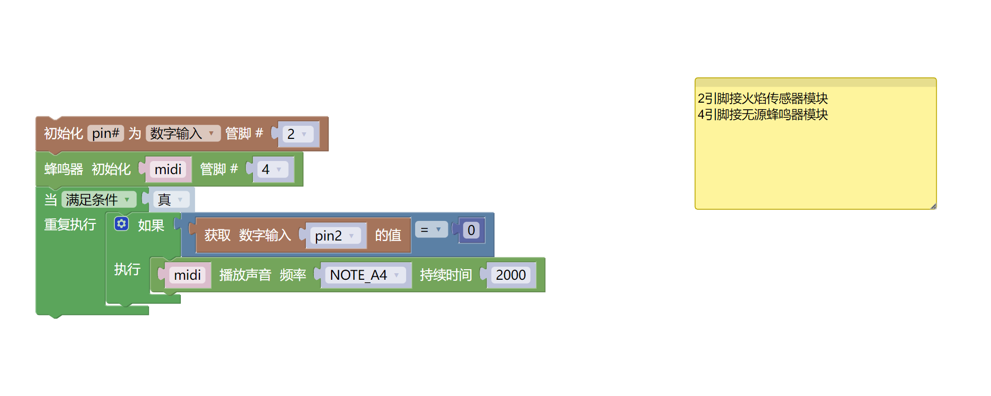
Example Program (ESP32 Development Board):Click to download
Attention: If prompted with an error message about the library file during program upload, please import the library file first!
Download and import tutorial for Mixly IDE ESP32 library:Click to view
8. Setting up the Test Environment
Setting up the Arduino Environment
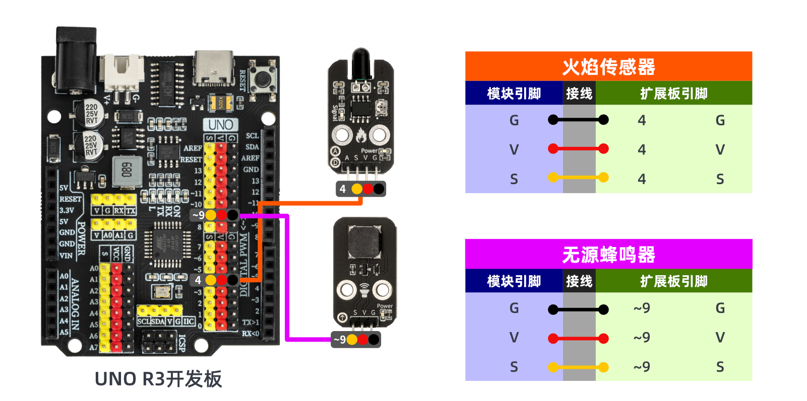
Prepare Components:
HELLO STEM UNO R3 PRO DEVELOPMENT BOARD *1
USB TYPE-C DATA CABLE *1
Passive Buzzer Module (HS-F02A) *1x
Flame sensor module (HS-S07A) *1
1P female to female Dupont wire *6 pieces or 3P female to female Dupont wire *2 pieces
Circuit wiring diagram:
ESP32 Test Environment Setup
Prepare Components:Pending update...
Circuit wiring diagram:Pending update...
9, Video tutorial
Video tutorial:Click to view
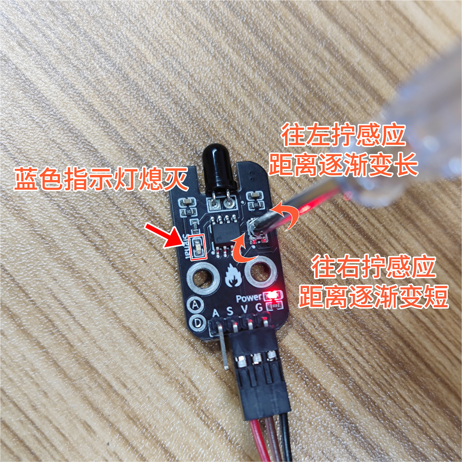
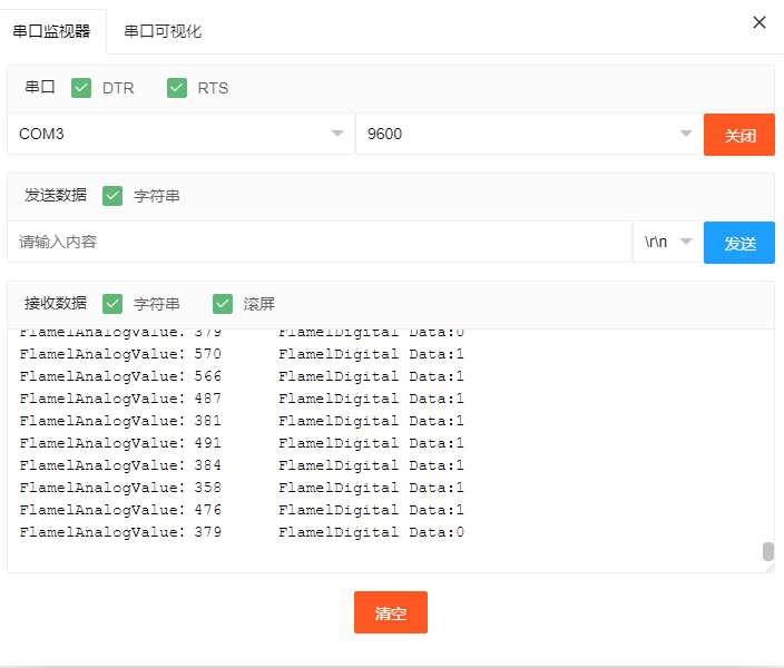
10, Test results
Arduino UNO test results:
In the case of the flame sensor module being powered on, adjust the module potentiometer with a small screwdriver, when the flame is detected, the sensor signal indicates the blue light is on, and when there is no flame detected, the module signal indicates the blue light is off.