
1. Introduction
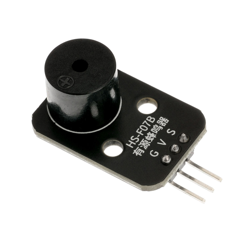
Some appliances often emit a buzzing sound in electrical state, which actually comes from a buzzer, and the讨厌的铃声disliked bell in school is just a bigger buzzer.There are two types of buzzers, one is an active buzzer and the other is a passive buzzer.The terms 'active' and 'passive' do not refer to whether power needs to be supplied, but rather to whether the buzzer has an internal oscillator or not.If you power it on, the active buzzer will make a buzzing sound, but the frequency is fixed.A passive buzzer is a buzzer without an internal oscillator, which does not produce a buzzing sound when powered on. It requires a 2~5 kHz square wave drive, and then different frequency waveforms will produce corresponding sounds.The buzzer module has three pins, where the pin marked '-' is grounded (GND), the middle pin is connected to 5V, and the pin marked "S" is connected to the signal (digital I/O).
2. Schematic
Active buzzer-HS-F07B schematicClick to view
Module Parameters
Pin Name | description |
|---|---|
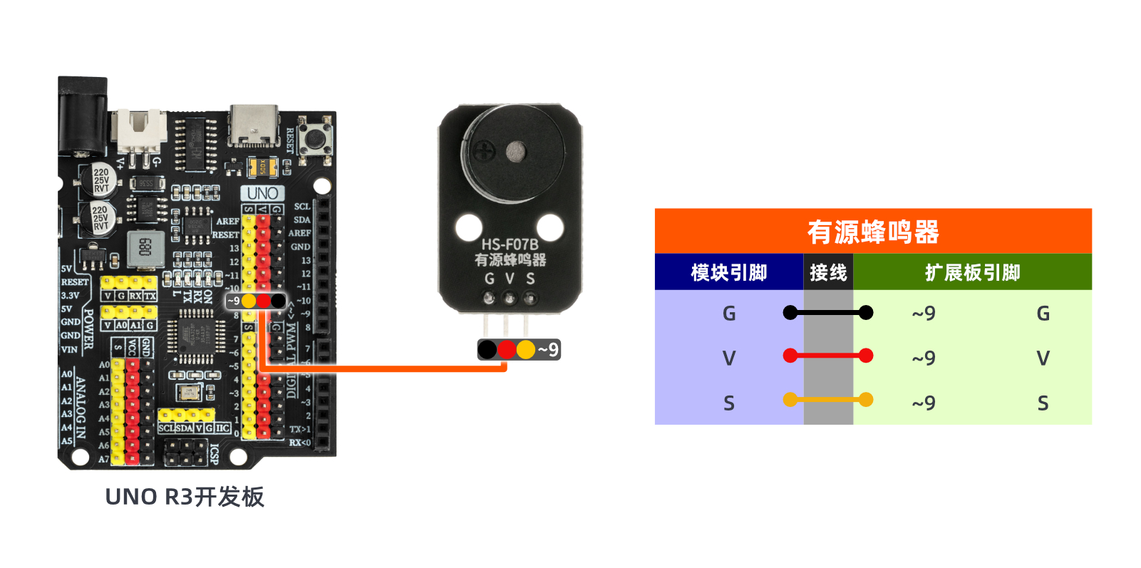
G | GND (Negative Power Input) |
V | VCC (Positive Power Input) |
S | Digital Signal Pin |
Power Supply Voltage: 3.3V / 5V
Connection Type: 2.54mm Header
Installation Method: Double Screw Fixed
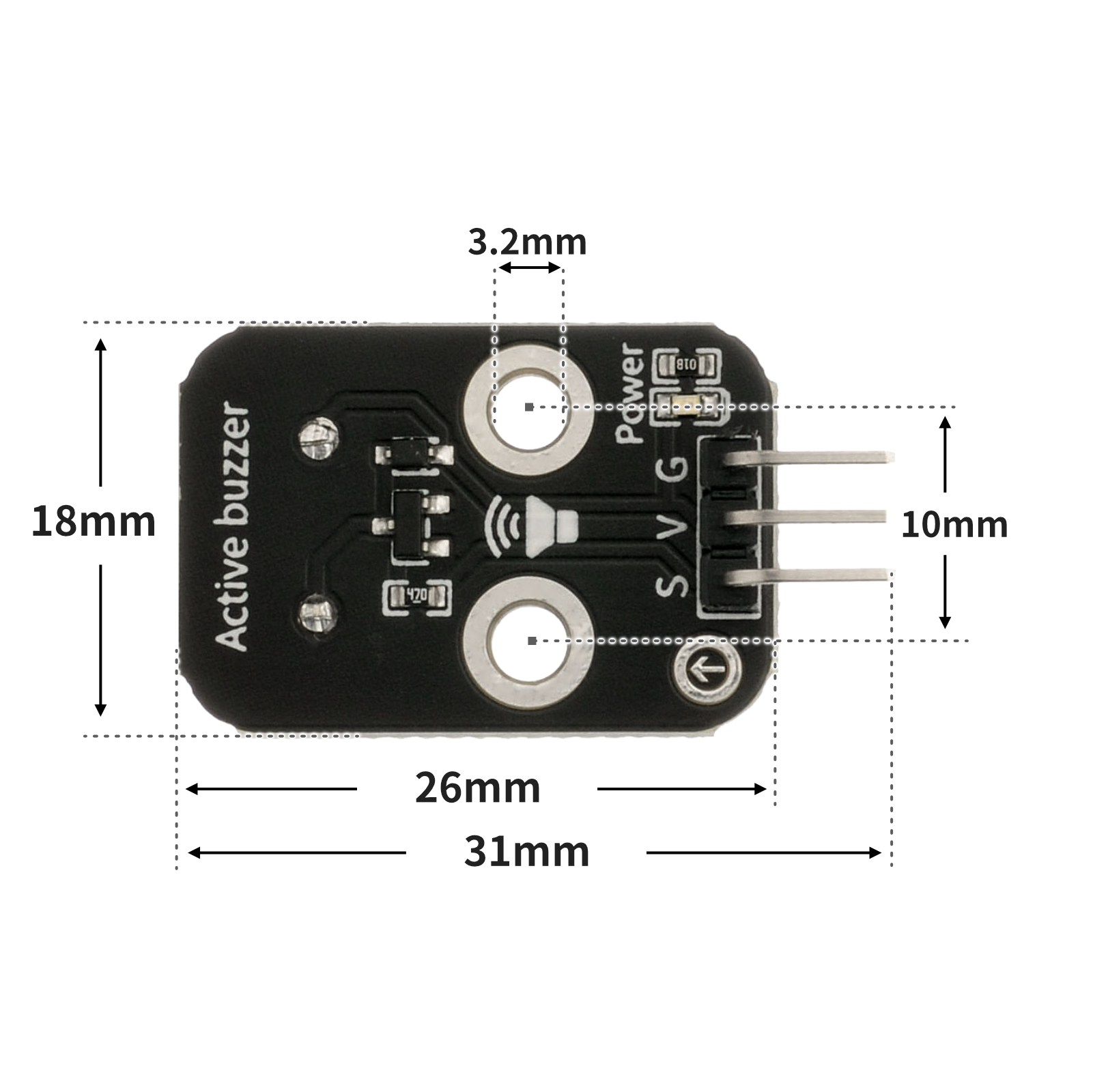
4, Circuit Board Size
5 of Arduino IDE example program
Attention: If prompted with an error message about the library file during program upload, please import the library file first!
Arduino IDE Library Download and Import Tutorial:Click to view
Example program (UNO development board):
/***********************************************************
  文件名:02_1activeBuzzer.ino
  描述:Arduino uno 控制蜂鸣器发出sos求救声。
  作者:chenzhiqiang
  日期:2022.10.15
  有源蜂鸣器模拟SOS信号\蜂鸣器:D9
***********************************************************/

int buzzerPin = 9; //定义数字9引脚为控制蜂鸣器的引脚
void setup(){
  pinMode(buzzerPin, OUTPUT);//设置数字9口模式,OUTPUT为输出
}


void loop(){

  my_3duan();//蜂鸣器频率快响三次
  delay(500);//设置延迟时间,500ms
  my_3chang();//蜂鸣器频率慢响三次
  delay(500);//设置延迟时间,500ms
  my_3duan();//蜂鸣器频率快响三次
  delay(500);//设置延迟时间,500ms

}
void my_3duan() {
  //蜂鸣器频率快响三次函数
  for (int i = 1; i <= 3; i = i + (1)) {
    digitalWrite(buzzerPin,HIGH);
    delay(200);
    digitalWrite(buzzerPin,LOW);
    delay(200);
  }
}

void my_3chang() {
  //蜂鸣器频率慢响三次函数
  for (int i = 1; i <= 3; i = i + (1)) {
    digitalWrite(buzzerPin, HIGH);
    delay(400);
    digitalWrite(buzzerPin, LOW);
    delay(400);
  }
}
6, ESP32 Python Example (for Mixly IDE/Misashi)
Choose the development board Python ESP32 [ESP32 Generic(4MB)] and upload in code mode
Attention: If prompted with an error message about the library file during program upload, please import the library file first!
Download and import tutorial for Mixly IDE ESP32 library:Click to view
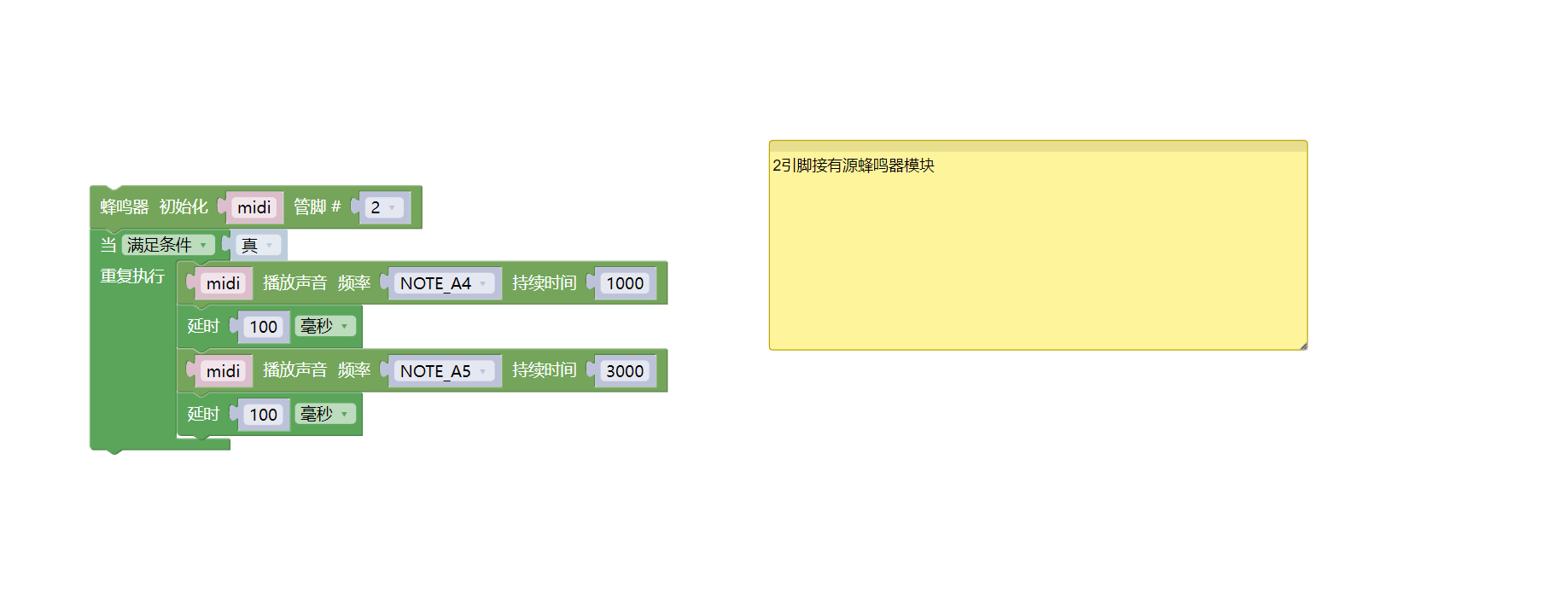
Example program (ESP32-Python):
import music
import time
midi = music.MIDI(2)
while True:
midi.pitch_time(440, 1000)
time.sleep_ms(100)
midi.pitch_time(880, 3000)
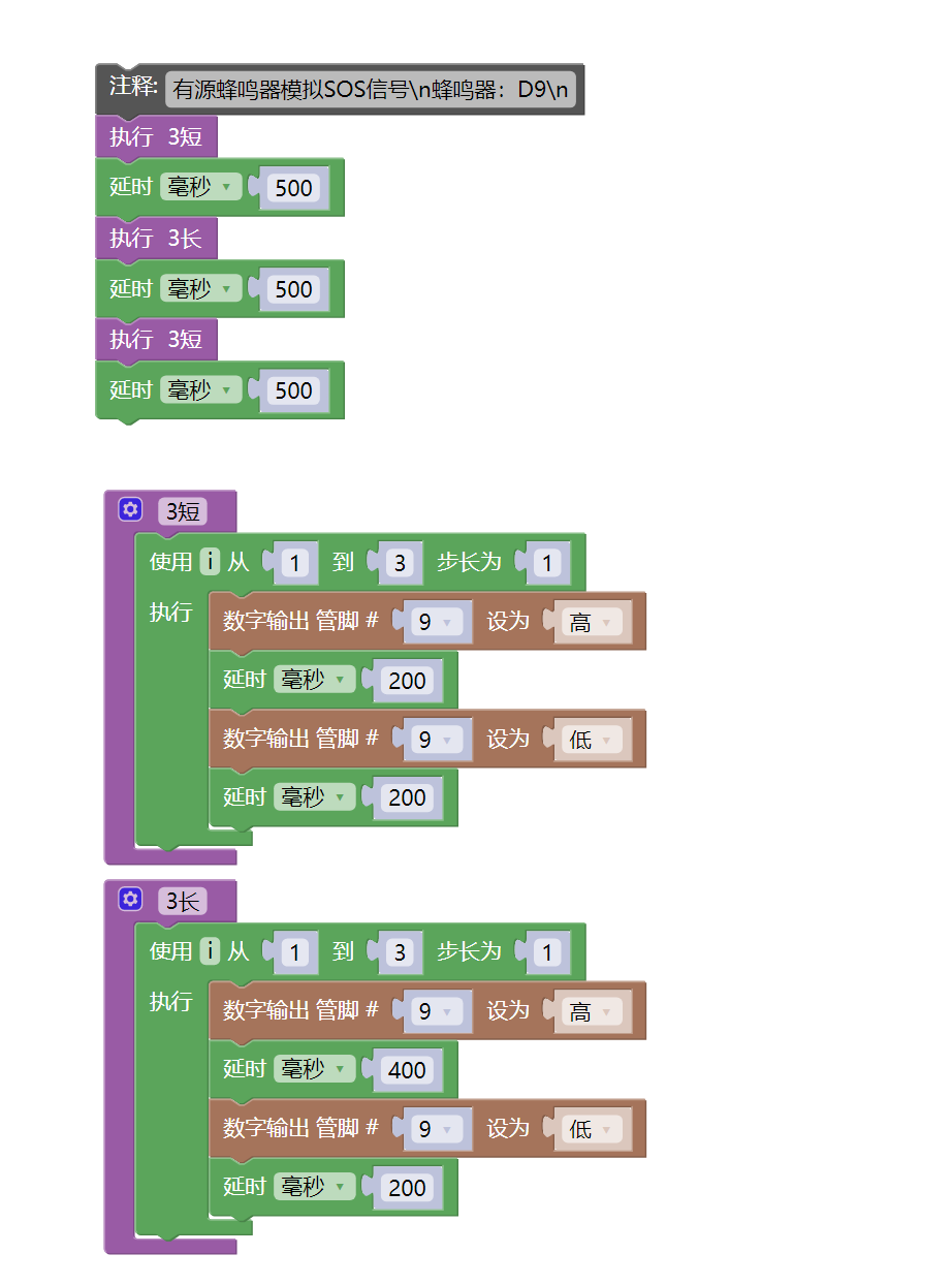
time.sleep_ms(100)7, Mixly example program (graphical language)
Example program (UNO development board):Click to download
Attention: If prompted with an error message about the library file during program upload, please import the library file first!
Download and import tutorial of Mixly IDE Arduino library:Click to view
Example Program (ESP32 Development Board):Click to download
Attention: If prompted with an error message about the library file during program upload, please import the library file first!
Download and import tutorial for Mixly IDE ESP32 library:Click to view
8. Setting up the Test Environment
Arduino UNO Test Environment Setup
Prepare Components:
HELLO STEM UNO R3 PRO DEVELOPMENT BOARD *1
USB TYPE-C DATA CABLE *1
Active Buzzer Module (HS-F07A/B) *1
1P female to female DuPont wire *3 pieces or 3P female to female DuPont wire *1 piece
Circuit wiring diagram:
ESP32 Test Environment Setup
Prepare Components:Pending update...
Circuit wiring diagram:Pending update...
9, Video tutorial
Video tutorial:Click to view
10, Test results
Arduino UNO test results:
After connecting the device, upload the above program to the Arduino UNO development board, then power on the U+ program cartoon, and the active buzzer will emit SOS distress sounds.