
1. Introduction
The ESP32 S3 (expansion board) is a配套 expansion board designed based on the development board EPS32-S3, integrating the pins of the development board onto a PCB circuit board.This expansion board is compatible with all EPS32-S3 series development boards.The circuit board is equipped with a PH2.0 interface while also retaining pin headers to meet the different wiring needs of users.
2, Characteristics
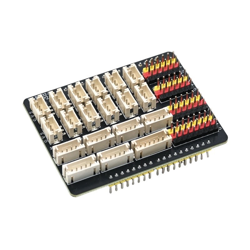
1, There are digital IO pin headers (pin numbers: 0-16, 21) and analog IO pin headers (pin numbers: 38-42, 45-46). (This can meet the need for connecting extension modules with Dupont wires)
2, there are digital IO ports PH2.0 3P sockets (pin numbers: 2, 4, 12, 13, 14, 15) and analog IO ports PH2.0 3P sockets (pin numbers: 32, 33, 34, 35, 36, 39), as well as 4 PH2.0 4P sockets, 2 PH2.0 5P sockets, and 1 PH2.0 6P socket.
3, featuring SPI communication interface pins, serial communication interface pins, I2C communication interface pins.
3, Expansion Board Parsing
Digital IO port PH2.0 3P socket (2, 4, 12, 13, 14, 15) and digital IO port pin header (0, 2, 4, 12, 13, 14, 15, 1, 17, 25, 26, 27)
You can specify these IO ports as digital outputs, which means they can output high or low levels.
Simulated IO port PH2.0 3P socket (32, 33, 34, 35, 36, 39) and simulated IO port pin header (32, 33, 34, 35, 36, 39)
Can specify these IO ports for simulation input and simulation input.
P1 socket
This socket circuit is designed for VCC/38/39/GND for easy connection with some modules using PH2.0 4P interfaces. (Adaptable module: HS-SR04L)Ultrasonic Sensor)
P2 Socket
This socket circuit design is convenient to connect with some matching modules using a PH2.0 4P interface. (Adaptable module: HS-S63-L)TCS342 color sensor, HS-F14LTM1650 four-digit LED digital tube module, HS-F15LTM637 four-digit clock digital tube module, HS-F19LOLED display, HS-F21LLCD1602 display, )
P3 bracket
This socket circuit is designed as 40/41/VCC/GND for easy connection with some modules that use PH2.0 4P interfaces.Voice recognition control module& HS-F04LMotor drive module& HS-F20LMotor Module, HS-F10LMotor drive module, HS-S49PLMP3 Audio Broadcast Module, HS-F23-L1-digit digital tube, HS-S60-LBluetooth module)
P4 socket
The socket circuit is designed as 42/45/46/GND for convenient connection with some modules using the PH2.0 4P interface. (Compatible module: HS-F05LTraffic Signal Module, HS-F01LRGB LED Module)
P5 Socket
This sub-circuit is designed as 12/10/11/V/G for easy connection with some matching modules using PH2.0 5P interfaces. (For example, HS-F13L)8x8 dot matrix display moduleHS-F24-L1-digit digital tube)
P6 seat
This socket circuit is designed as 48/18/17/V/G for easy connection with some modules using PH2.0 5P interfaces. (Compatible module: HS-S34L)Dual-axis joystick moduleHS-S32LRotary encoder)
P7 socket
The socket circuit is designed to be compatible with some modules using the PH2.0 6P interface for connection. (Compatible module: HS-KEY4L4P button module)