
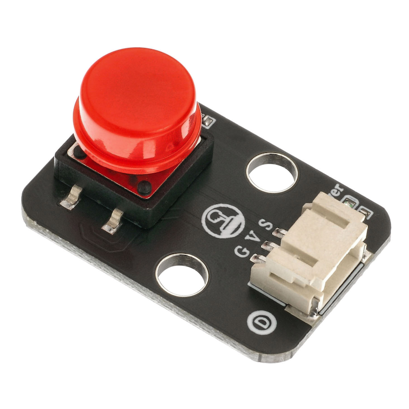
1. Introduction
2. Schematic
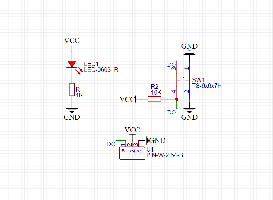
Module Parameters
Pin Name | description |
|---|---|
G | GND (Negative Power Input) |
V | VCC (Positive Power Input) |
S | Digital Signal Pin |
Power Supply Voltage: 3.3V / 5V
Connection method: PH2.0 terminal wire
Installation method: Modular fixed
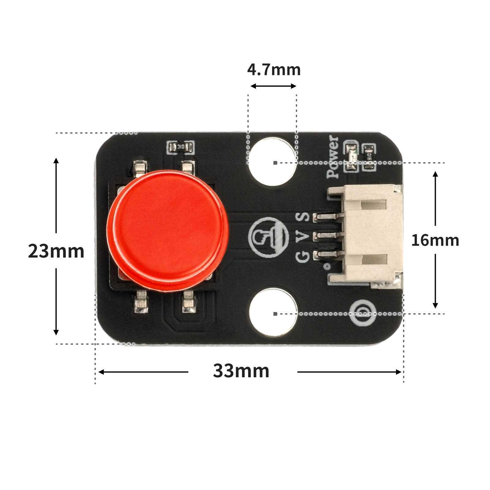
4, Circuit Board Size
5 of Arduino IDE example program
Arduino UNO Example (for Mixly IDE, Arduino IDE):
void setup(){
 Serial.begin(9600);
 pinMode(4, INPUT);
 pinMode(6, OUTPUT);
}
void loop(){
 if (digitalRead(4) == LOW) {
 digitalWrite(6,HIGH);
 } else {
 digitalWrite(6,LOW);
 }
 Serial.println(digitalRead(4));
}
ESP32 Python Example (for Mixly IDE / Micskit)
(Choose the Python ESP32 [ESP32 Generic(4MB)] to switch to code mode upload):
import machine
import time
pin2 = machine.Pin(2, machine.Pin.IN)
pin4 = machine.Pin(4, machine.Pin.OUT)
while True:
if pin2.value() == 0:
pin4.value(1)
time.sleep(1)
else:
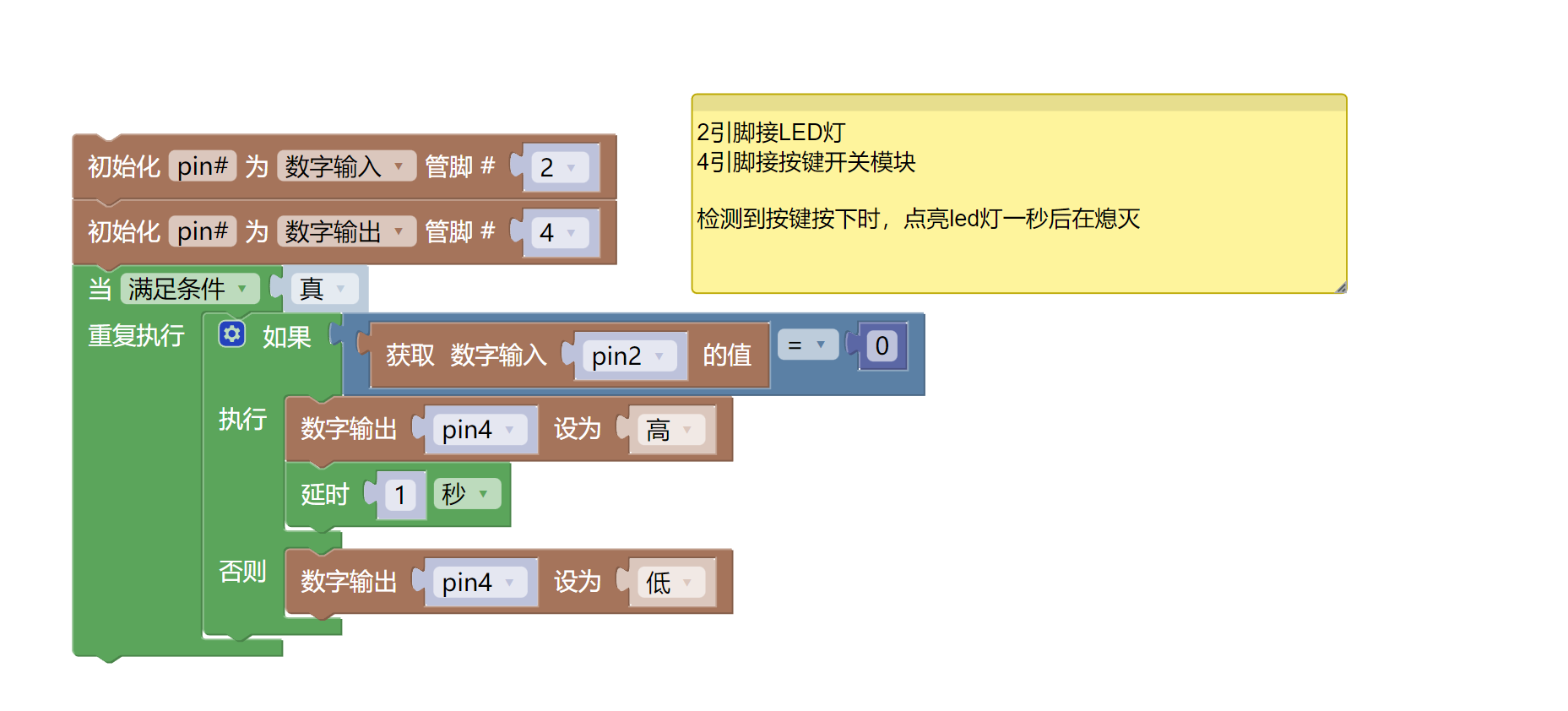
pin4.value(0)6, Miciqi Mixly Example Program (Graphical Language)
Example program (UNO development board):Click to download

Example Program (ESP32 Development Board):Click to download
7, Test Environment Setup
Arduino UNO Test Environment Setup
Prepare Components:
HELLO STEM UNO R3 DEVELOPMENT BOARD *1
HELLO STEM UNO R3 P EXPANSION BOARD *1
USB TYPE-C DATA CABLE *1
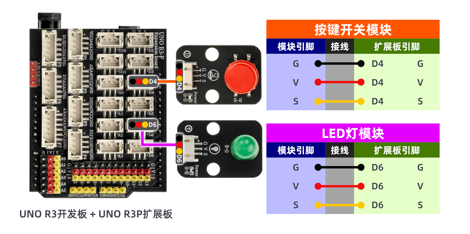
LED module (HS-F08L) *1
Push-button switch module (HS-KEY1L) *1
PH2.0 3P Dupont wire *2
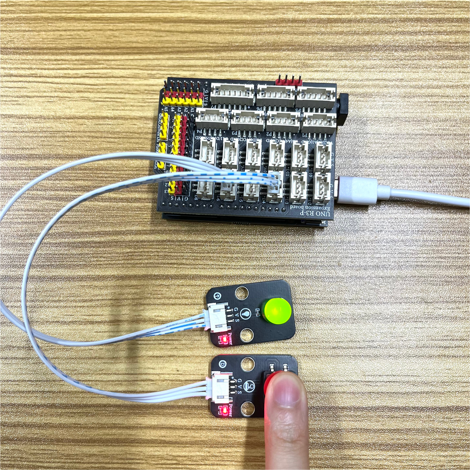
Circuit wiring diagram:
ESP32 Python test environment setup
8. Video tutorial
Arduino UNO video tutorial:Click to view
ESP32 Python Video Tutorial:
9. Test conclusion
Arduino UNO Test Conclusion:
ESP32 Python test conclusion: