
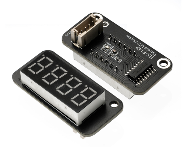
1. Introduction
2. Schematic
TM1650 Four-Digit Tube-HS-F14P SchematicClick to view
Module Parameters
Pin Name | description |
|---|---|
VCC | VCC (Positive Power Input) |
GND | GND (Negative Power Input) |
SDA | Bidirectional Data Communication Pin |
SCL | Clock Signal Communication Pin |
Power Supply Voltage: 3.3V / 5V
Connection method: PH2.0 terminal wire
Installation Method: Double Screw Fixed
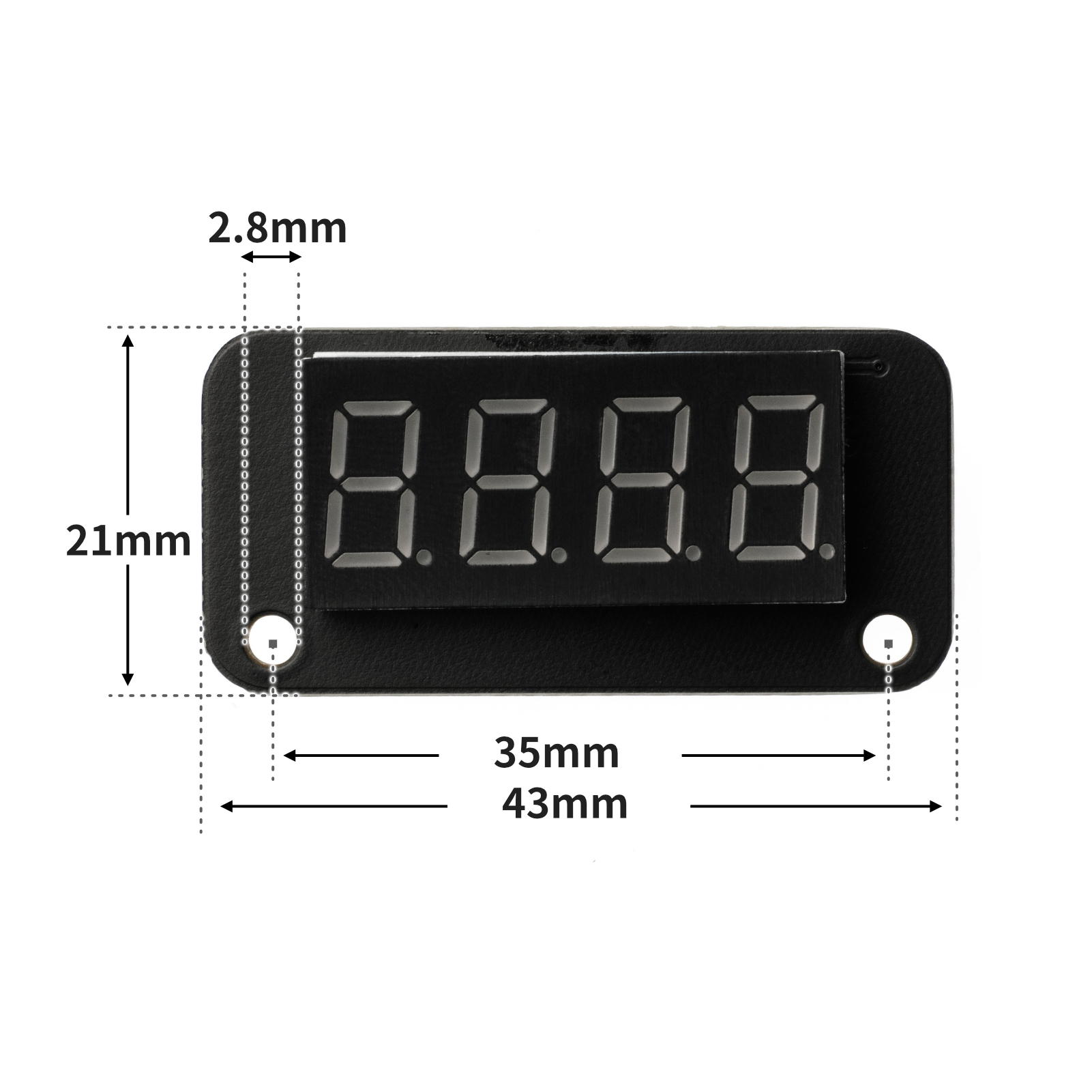
4, Circuit Board Size
5 of Arduino IDE example program
Attention: If prompted with an error message about the library file during program upload, please import the library file first!
Arduino IDE Library Download and Import Tutorial:Click to view
Example program (UNO development board):
#include <Wire.h>
#include <TM1650.h>
#include <SimpleTimer.h>

volatile int item;
TM1650 tm_4display;
SimpleTimer timer;

void Simple_timer_1() {
  tm_4display.displayString(String(item));
  item = item + 1;
}

void setup(){
  item = 0;
  //IIC接口连接TM1650数码管\n每隔一秒显示数增加1
  Wire.begin();
  tm_4display.init();
  timer.setInterval(1000L, Simple_timer_1);

}

void loop(){
  timer.run();

}
6, ESP32 Python Example (for Mixly IDE/Misashi)
Choose the development board Python ESP32 [ESP32 Generic(4MB)] and upload in code mode
Attention: If prompted with an error message about the library file during program upload, please import the library file first!
Download and import tutorial for Mixly IDE ESP32 library:Click to view
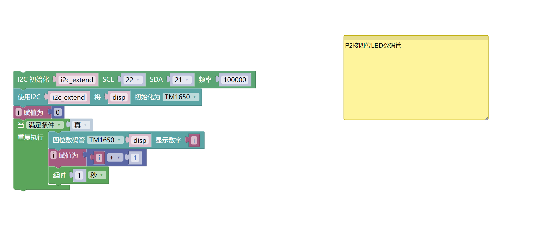
Example program (ESP32-Python):
import machine
import tm1650
import time
i2c_extend = machine.SoftI2C(scl = machine.Pin(22), sda = machine.Pin(21), freq = 100000)
disp = tm1650.TM1650(i2c_extend)
i = 0
while True:
disp.shownum(i)
i = i + 1
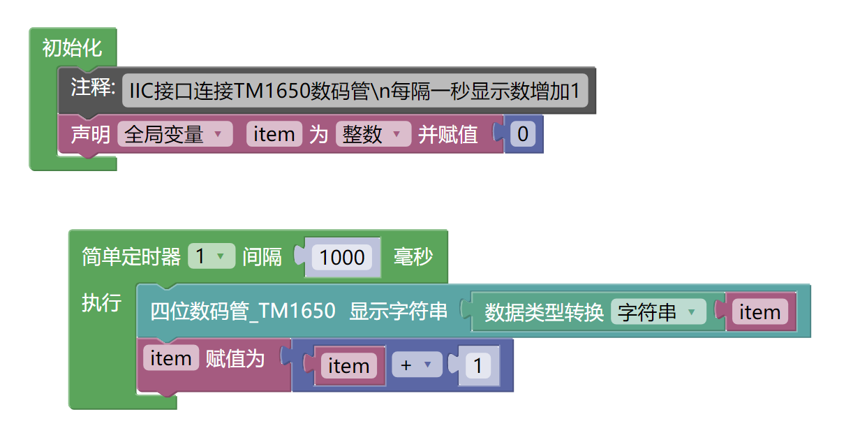
time.sleep(1)7, Mixly example program (graphical language)
Example program (UNO development board):Click to download
Attention: If prompted with an error message about the library file during program upload, please import the library file first!
Download and import tutorial of Mixly IDE Arduino library:Click to view
Example Program (ESP32 Development Board):Click to download
Attention: If prompted with an error message about the library file during program upload, please import the library file first!
Download and import tutorial for Mixly IDE ESP32 library:Click to view
8. Setting up the Test Environment
Arduino UNO Test Environment Setup
Prepare Components:
HELLO STEM UNO R3 DEVELOPMENT BOARD *1
HELLO STEM UNO R3 P EXPANSION BOARD *1
USB TYPE-C DATA CABLE *1
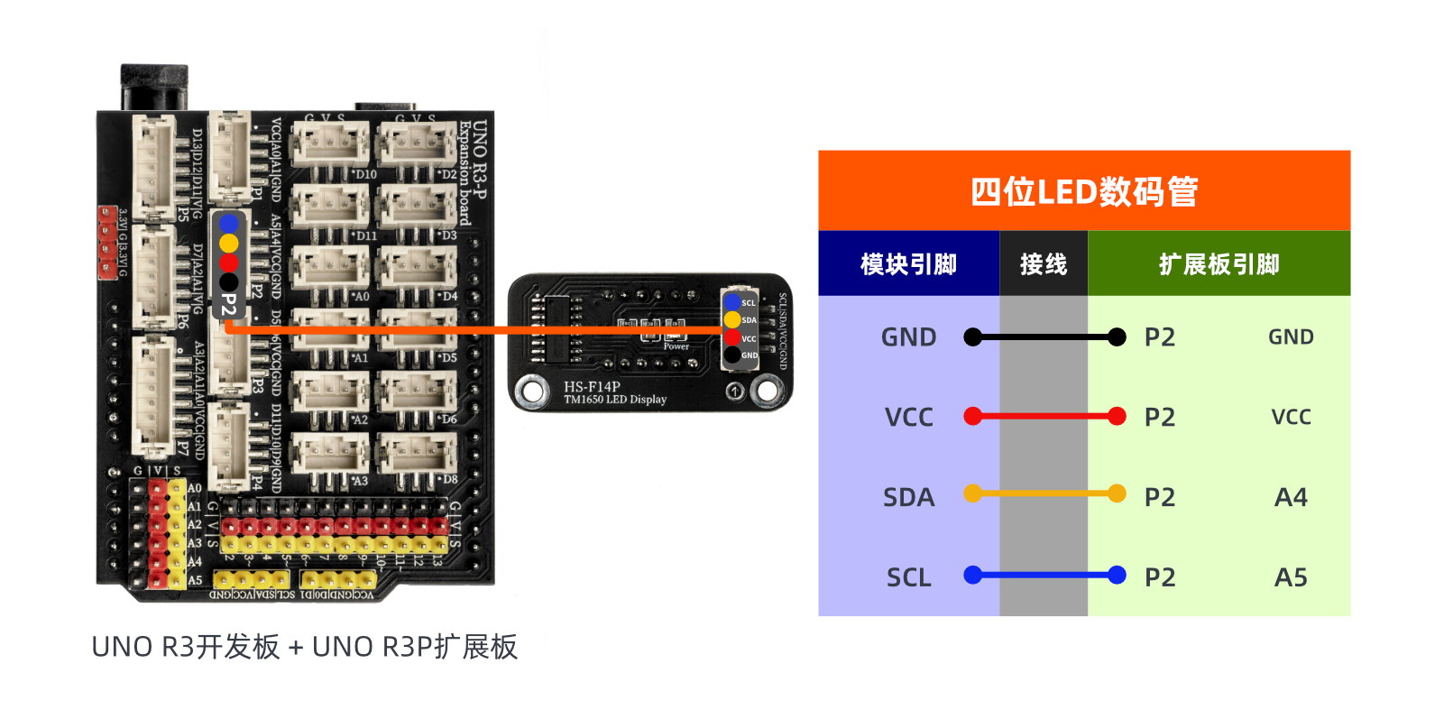
TM1650 four-digit LED display module (HS-F14P) *1
PH2.0 4P socket to Dupont wire *1 or PH2.0 4P double-ended socket wire *1
Circuit wiring diagram:
ESP32 Test Environment Setup
Prepare Components:Pending update...
Circuit wiring diagram:Pending update...
9, Video tutorial
Video tutorial:Click to view
10, Test conclusion
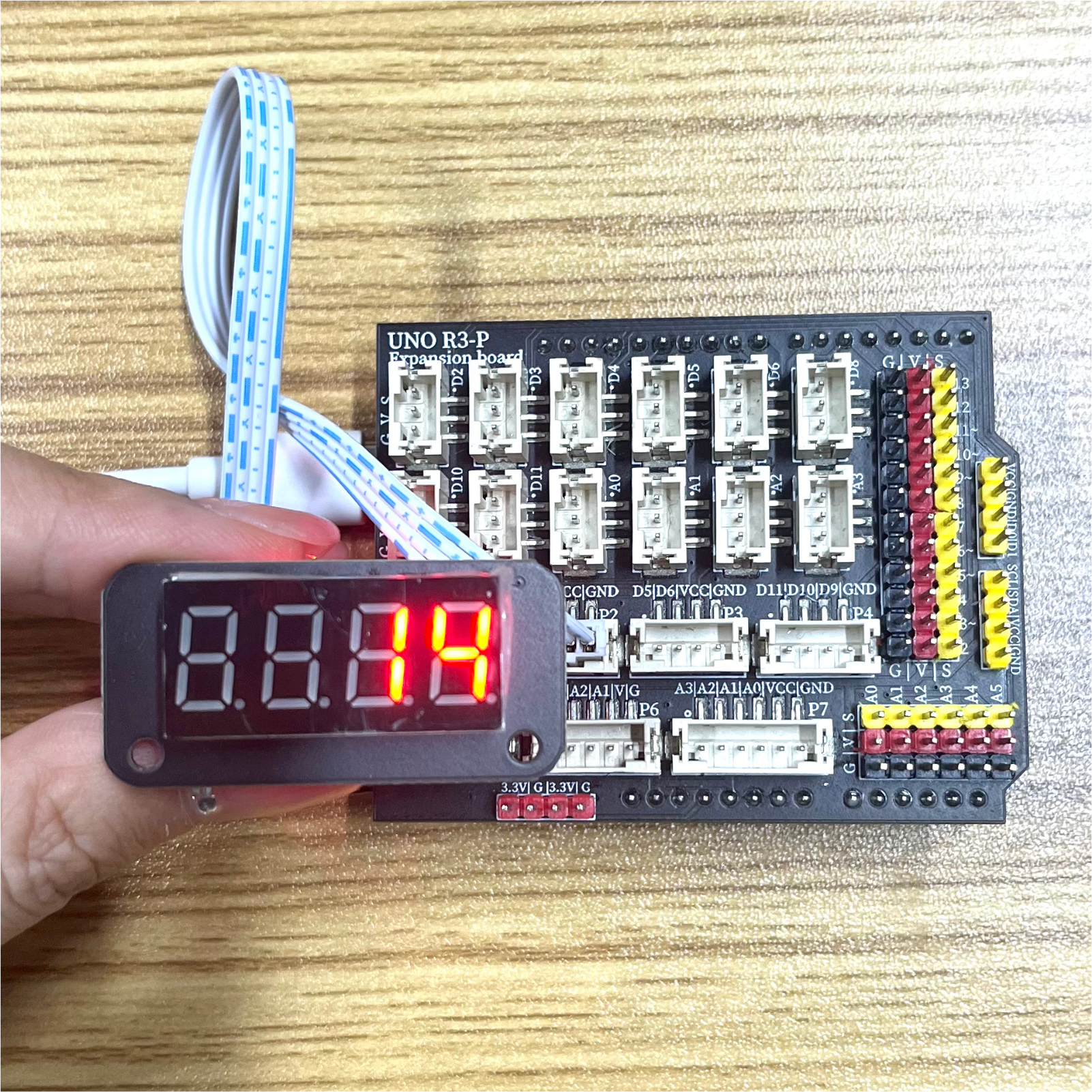
Arduino UNO test results:
After the device is connected and the program mentioned above is uploaded to the Arduino UNO development board, you will find that the seven-segment display automatically increments the number every second.
ESP32 Test Results:
Pending update...