
1. Introduction
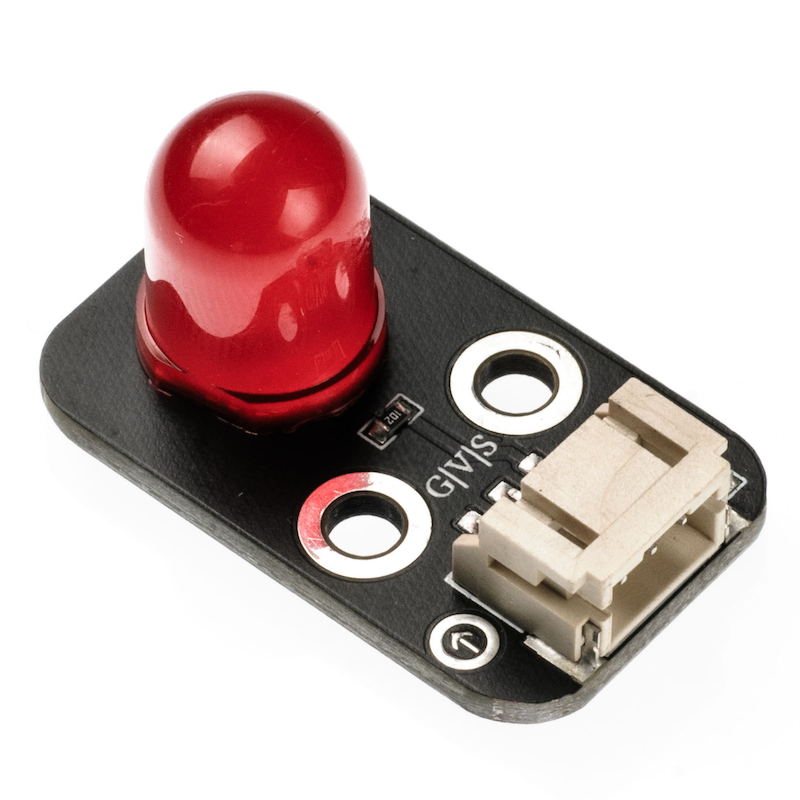
LED lamps are also known as light-emitting diodes, made of mixed compounds, namely gallium (Ga), arsenic (AS), and phosphorus (P).Gallium phosphide diodes emit red light, gallium phosphide diodes emit green light, silicon carbide diodes emit yellow light.The reverse breakdown voltage of the LED is 5V.The positive伏安特性曲线too steep,must be connected in series with a limiting resistor,in order to control the current flowing through the pipeline when in use.
2. Schematic
LED light HS-F08P schematicClick to view
Module Parameters
Pin Name | description |
|---|---|
G | GND (Negative Power Input) |
V | VCC (Positive Power Input) |
S | Digital Signal Pin |
Power Supply Voltage: 3.3V / 5V
Connection type: PH2.0 3P terminal wire
Installation Method: Double Screw Fixed
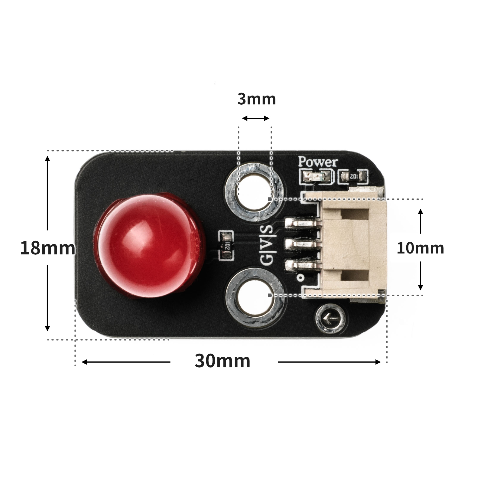
4, Circuit Board Size
5 of Arduino IDE example program
Attention: If prompted with an error message about the library file during program upload, please import the library file first!
Arduino IDE Library Download and Import Tutorial:Click to view
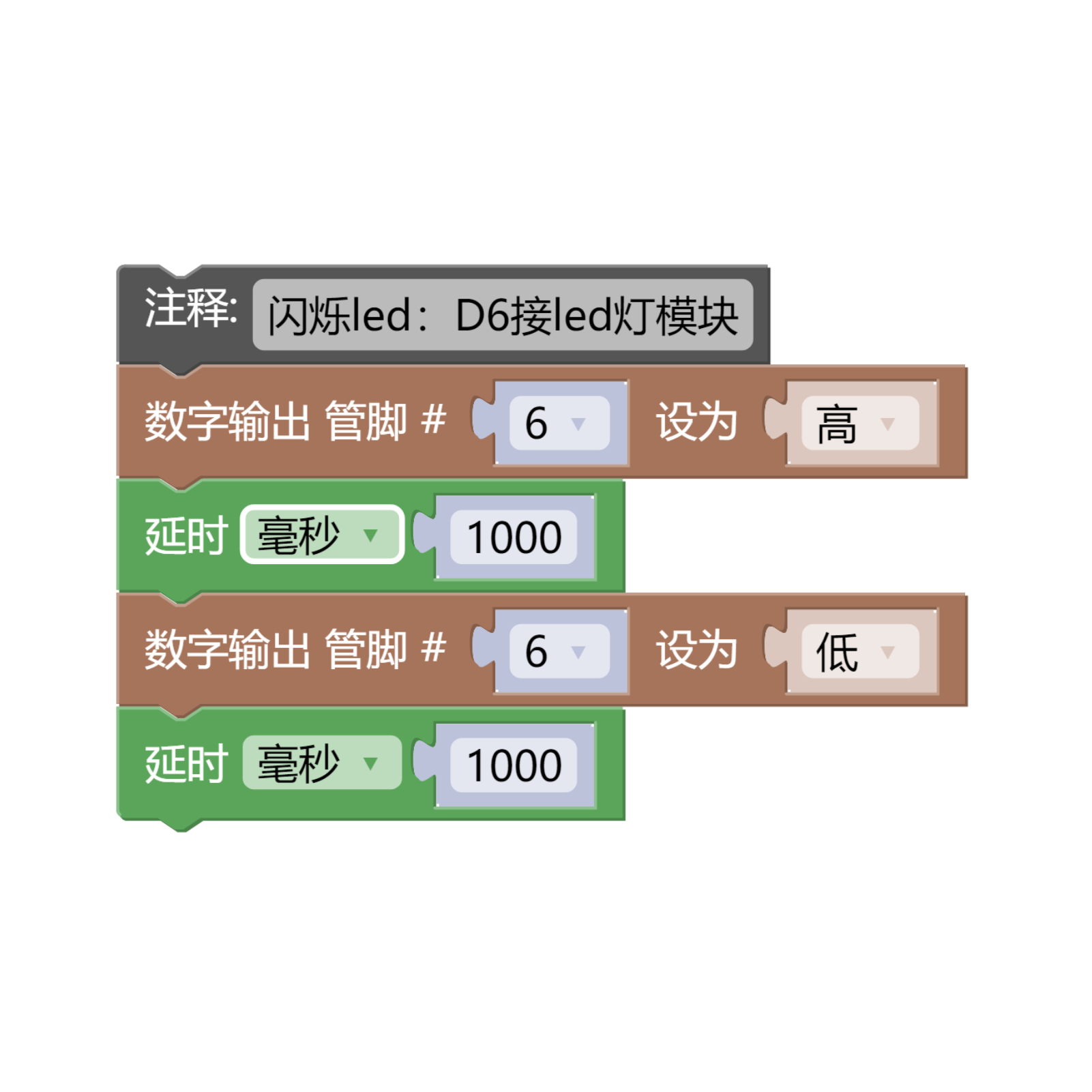
Example program (UNO development board):
int ledPin=6; //定义数字6引脚为控制LED的引脚
void setup()
{
pinMode(ledPin,OUTPUT); //设置数字6口模式,OUTPUT:输出模式
}
void loop()
{
digitalWrite(ledPin,HIGH); //HIGH设置为5V左右 PIN6
delay(1000); //设置延迟时间,1000 = 1S
digitalWrite(ledPin,LOW); //LOW设置为5V左右 PIN6
delay(1000); //设置延迟时间,1000 = 1S
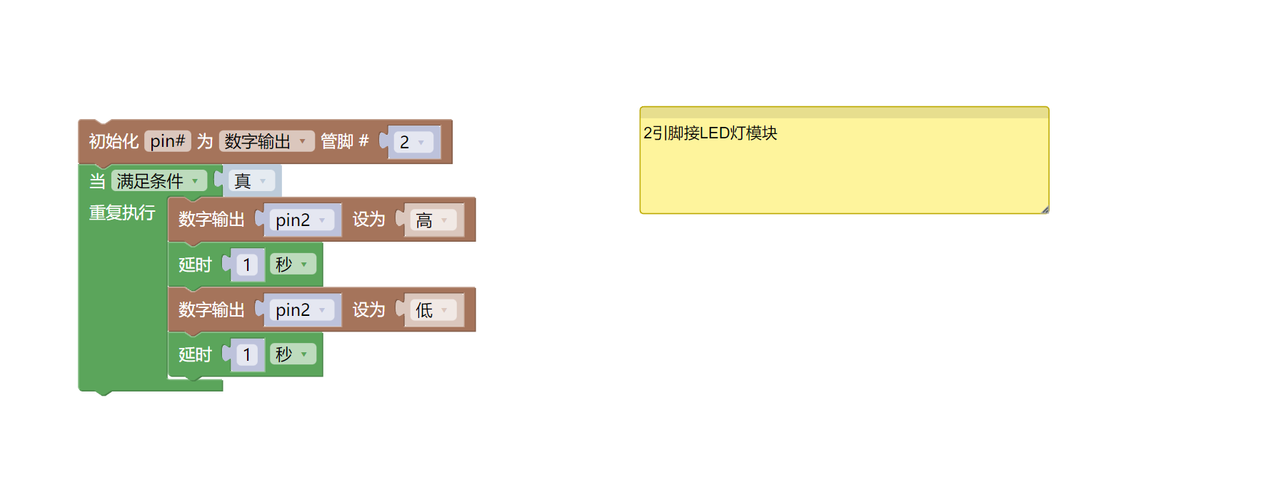
} 6, ESP32 Python Example (for Mixly IDE/Misashi)
Choose the development board Python ESP32 [ESP32 Generic(4MB)] and upload in code mode
Attention: If prompted with an error message about the library file during program upload, please import the library file first!
Download and import tutorial for Mixly IDE ESP32 library:Click to view
Example program (ESP32-Python):
import machine
import time


pin2 = machine.Pin(2, machine.Pin.OUT)
while True:
    pin2.value(1)
    time.sleep(1)
    pin2.value(0)
    time.sleep(1)
7, Mixly example program (graphical language)
Example program (UNO development board):Click to download
Attention: If prompted with an error message about the library file during program upload, please import the library file first!
Download and import tutorial of Mixly IDE Arduino library:Click to view
Example Program (ESP32 Development Board):Click to download
Attention: If prompted with an error message about the library file during program upload, please import the library file first!
Download and import tutorial for Mixly IDE ESP32 library:Click to view
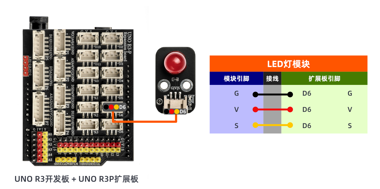
8. Setting up the Test Environment
Arduino UNO Test Environment Setup
Prepare Components:
HELLO STEM UNO R3 PRO DEVELOPMENT BOARD *1
HELLO STEM UNO R3 P EXPANSION BOARD *1
USB TYPE-C DATA CABLE *1
LED module (HS-F08P) *1
PH2.0 3P Connector to DuPont Wire *1 or PH2.0 3P Dual Head Connector Wire *1
Circuit wiring diagram:
ESP32 Test Environment Setup
Prepare Components:Updated with...
Circuit wiring diagram:Updated with...
9, Video tutorial
Video tutorial:Click to view
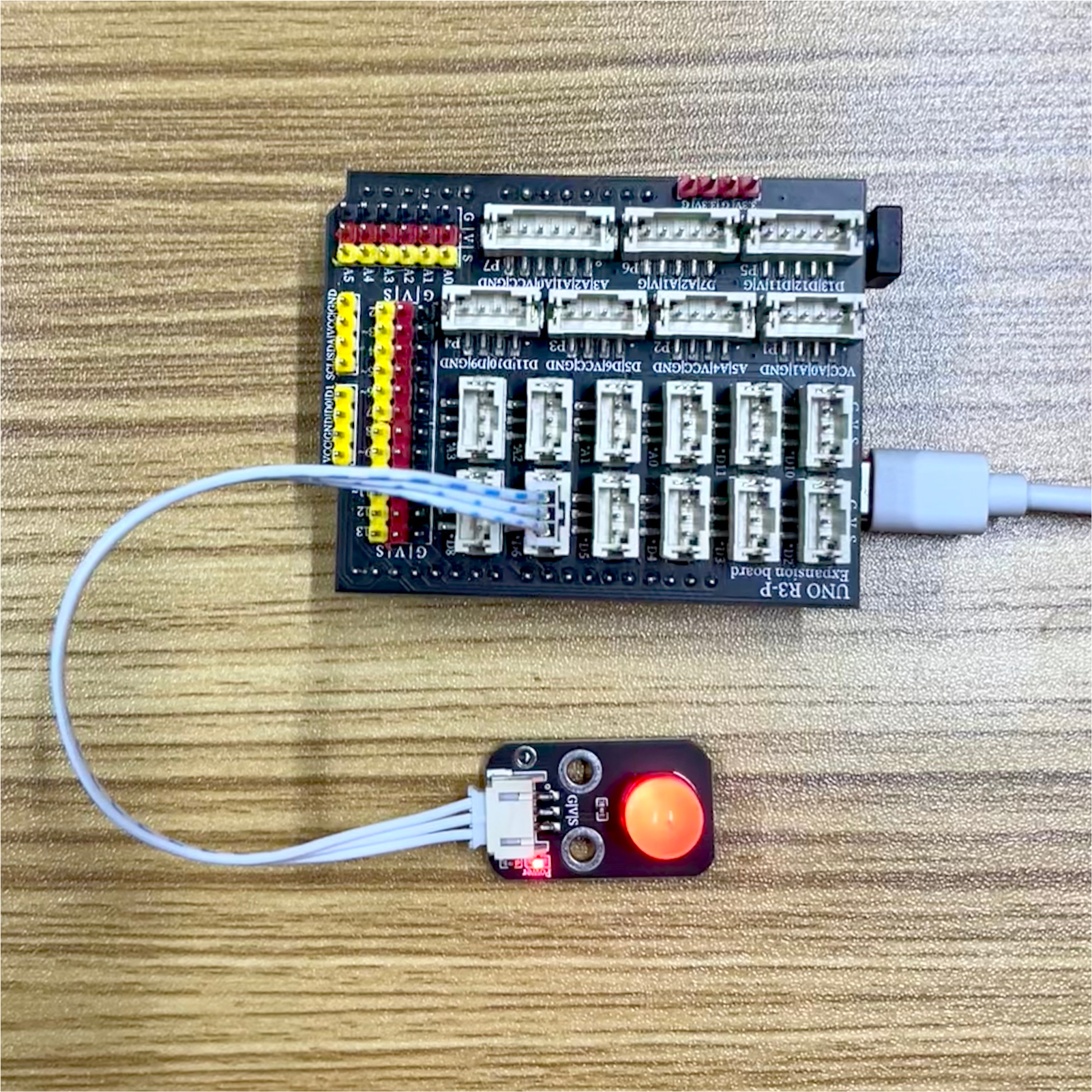
10, Test results
Arduino UNO test results:
After the device is connected and the program above is uploaded to the UNO R3 PRO development board, you will find that the LED light will blink at a frequency of 1 second on and 1 second off, achieving the effect we want.
ESP32 Test Results:
Pending update...