
1. Introduction
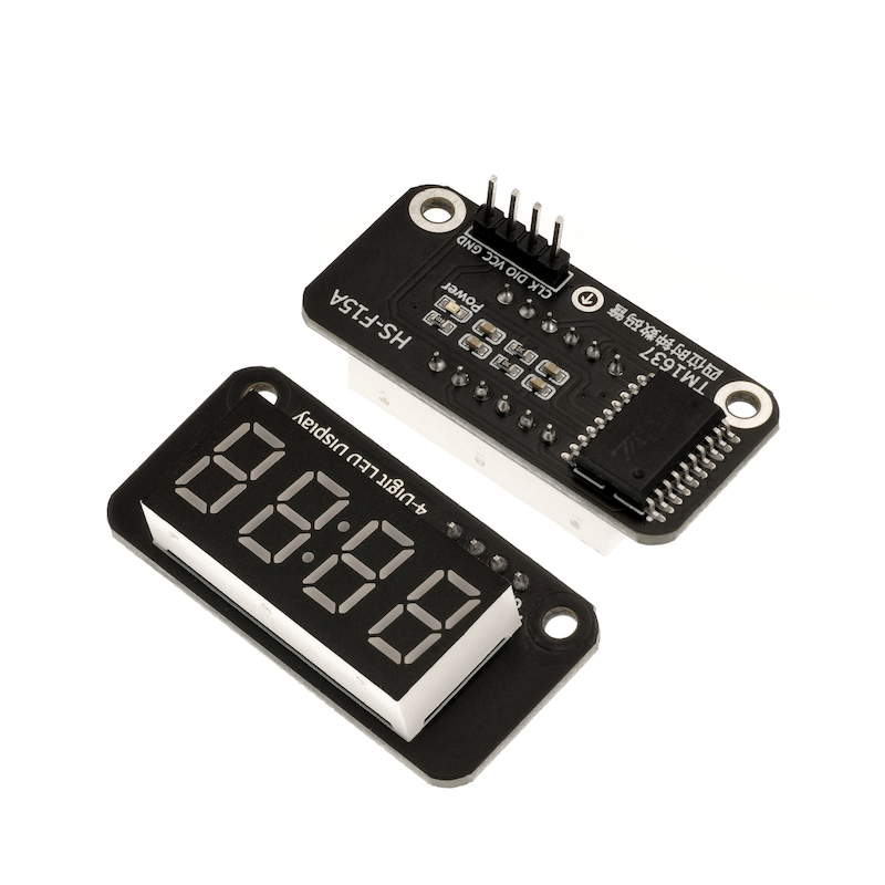
A 4-digit 7-segment display is composed of a 4-digit 7-segment common anode display with 12 pins and a control chip TM1637.The other side is the icon symbol of the digital tube.This product can be applied to time display, stopwatch display, and other devices that need to display numbers.
2. Schematic
TM1637 four-digit clock tube-HS-F15A schematic diagramClick to view
Module Parameters
Pin Name | description |
|---|---|
VCC | VCC (Positive Power Input) |
GND | GND (Negative Power Input) |
SDA | Bidirectional Data Communication Pin |
SCL | Clock Signal Communication Pin |
Power Supply Voltage: 3.3V / 5V
Connection Type: 2.54mm Header
Installation Method: Double Screw Fixed
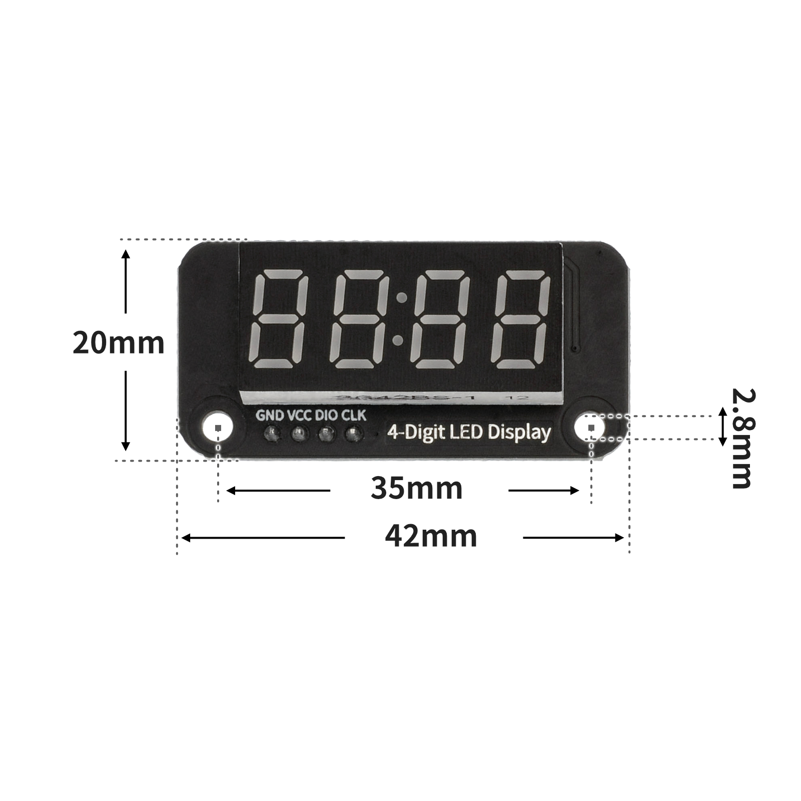
4, Circuit Board Size
5 of Arduino IDE example program
Attention: If prompted with an error message about the library file during program upload, please import the library file first!
Arduino IDE Library Download and Import Tutorial:Click to view
Example program (UNO development board):
#include <SevenSegmentTM1637.h>
SevenSegmentTM1637 display(9,10);
void setup(){
display.begin();
display.setBacklight(20);
}
void loop(){
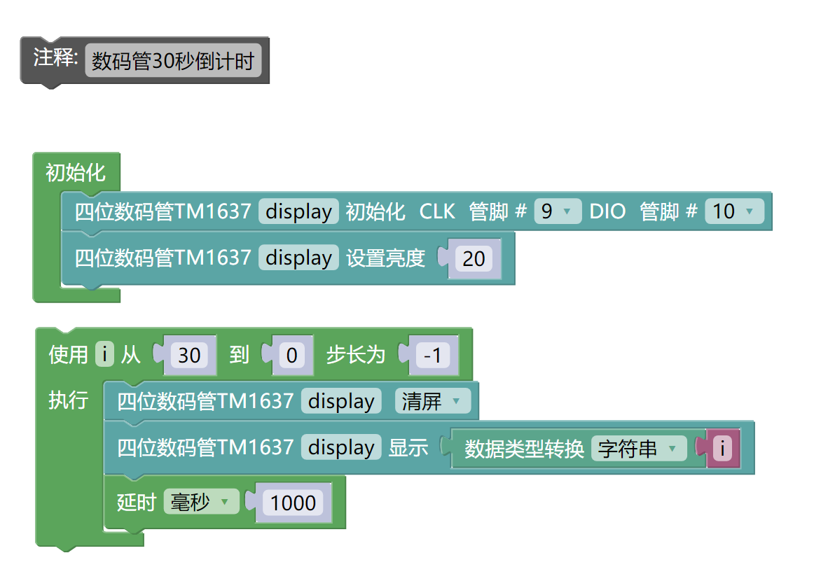
//数码管30秒倒计时
for (int i = 30; i >= 0; i = i + (-1)) {
display.clear();
display.print(String(i));
delay(1000);
}
}6, ESP32 Python Example (for Mixly IDE/Misashi)
Choose the development board Python ESP32 [ESP32 Generic(4MB)] and upload in code mode
Attention: If prompted with an error message about the library file during program upload, please import the library file first!
Download and import tutorial for Mixly IDE ESP32 library:Click to view
Example program (ESP32-Python):
from machine import Pin
from time import sleep_us
TM1637_CMD1 = 64 # 0x40 数据命令
TM1637_CMD2 = 192 # 0xC0 地址命令
TM1637_CMD3 = 128 # 0x80 显示控制命令
TM1637_DELAY = 10 # 10us延迟,用于clk/dio脉冲之间
# 数码管段码对应表 (0-15分别对应0-F)
_SEGMENTS = (0x3F,0x06,0x5B,0x4F,0x66,0x6D,0x7D,0x07,0x7F,0x6F,0x77,0x7C,0x39,0x5E,0x79,0x71)
# TM1637显示类
class TM1637():
"""
@brief 初始化函数
@param clk:clk引脚定义
@param dio:dio引脚定义
@param intensity:亮度 默认7
@param number:数码管位数,默认4位
"""
def __init__(self, clk, dio, intensity=7, number = 4):
self.clk = clk
self.dio = dio
self._intensity = intensity%8
self._LED = number
self._ON = 8
self.dbuf = [0, 0, 0, 0]
self.clk.init(Pin.OUT, value=0)
self.dio.init(Pin.OUT, value=0)
sleep_us(TM1637_DELAY)
self.clear()
"""@brief 发送起始信号"""
def _start(self):
self.dio(0)
sleep_us(TM1637_DELAY)
self.clk(0)
sleep_us(TM1637_DELAY)
"""@brief 发送停止信号"""
def _stop(self):
self.dio(0)
sleep_us(TM1637_DELAY)
self.clk(1)
sleep_us(TM1637_DELAY)
self.dio(1)
"""发送数据命令:自动地址递增,普通模式"""
def _write_data_cmd(self):
# automatic address increment, normal mode
self._start()
self._write_byte(TM1637_CMD1)
self._stop()
"""发送显示控制命令:设置显示开关和亮度"""
def _write_dsp_ctrl(self):
# display on, set brightness
self._start()
self._write_byte(TM1637_CMD3 | self._ON | self._intensity)
self._stop()
"""
向TM1637写入一个字节
param b: 要写入的字节
"""
def _write_byte(self, b):
for i in range(8):
self.dio((b >> i) & 1)
sleep_us(TM1637_DELAY)
self.clk(1)
sleep_us(TM1637_DELAY)
self.clk(0)
sleep_us(TM1637_DELAY)
self.clk(1)
sleep_us(TM1637_DELAY)
self.clk(0)
sleep_us(TM1637_DELAY)
"""打开显示"""
def on(self):
self._ON = 8
self._write_data_cmd()
self._write_dsp_ctrl()
"""关闭显示"""
def off(self):
self._ON = 0
self._write_data_cmd()
self._write_dsp_ctrl()
"""
@brief 设置或获取亮度
:param val: 亮度值(1-8),None则返回当前亮度
:return: 当前亮度值
"""
def intensity(self, val=None):
if val is None:
return self._intensity
val = max(0, min(val, 8))
if val == 0:
self.off()
else:
self._ON = 8
self._intensity = val-1
self._write_data_cmd()
self._write_dsp_ctrl()
"""
@brief 向指定位置写入数据
:param bit: 位置(0-3)
:param dat: 要显示的段码
"""
def _dat(self, bit, dat):
self._write_data_cmd()
self._start()
self._write_byte(TM1637_CMD2 | (bit%self._LED))
self._write_byte(dat)
self._stop()
self._write_dsp_ctrl()
"""清屏,所有位置显示空白"""
def clear(self):
self._dat(0, 0)
self._dat(1, 0)
self._dat(2, 0)
self._dat(3, 0)
self.dbuf = [0, 0, 0, 0]
"""
@brief 在指定位置显示单个数字或字符
:param num: 要显示的数字(0-15对应0-F)
:param bit: 位置(0-3)
"""
def showbit(self, num, bit = 0):
self.dbuf[bit%self._LED] = _SEGMENTS[num%16]
self._dat(bit, _SEGMENTS[num%16])
"""
@brief 打开时钟点
@param show: True显示,False隐藏
"""
def showDP(self, bit = 1, show = True):
bit = bit%self._LED
if show:
self._dat(bit, self.dbuf[bit] | 0x80)
else:
self._dat(bit, self.dbuf[bit] & 0x7F)
"""
@brief显示整数或小数
@param num: 要显示的数字(整数或小数)
"""
def shownum(self, num):
self.clear()
DP=False
if isinstance(num,float):
num=int(num*10)
DP=True
if num < 0:
self._dat(0, 0x40) # '-'
num = -num
elif num >= 1000:
self.showbit((num // 1000) % 10)
self.showbit(num % 10, 3)
if num >= 10:
self.showbit((num // 10) % 10, 2)
if num >= 100:
self.showbit((num // 100) % 10, 1)
if DP:
self.showDP(2)
"""
@brief 显示十六进制数
@param num: 要显示的十六进制数
"""
def showhex(self, num):
if num < 0:
self._dat(0, 0x40) # '-'
num = -num
else:
self.showbit((num >> 12) % 16)
self.showbit(num % 16, 3)
self.showbit((num >> 4) % 16, 2)
self.showbit((num >> 8) % 16, 1)
def ShowTime(self, H, M,DPshow = True):
H_1 = H // 10 % 10
H_2 = H % 10
M_1 = M // 10 % 10
M_2 = M % 10
self.showbit(H_1, 0)
self.showbit(H_2, 1)
self.showbit(M_1, 2)
self.showbit(M_2, 3)
if(DPshow == True):
self.showDP(show = True)
else:
self.showDP(show = False)
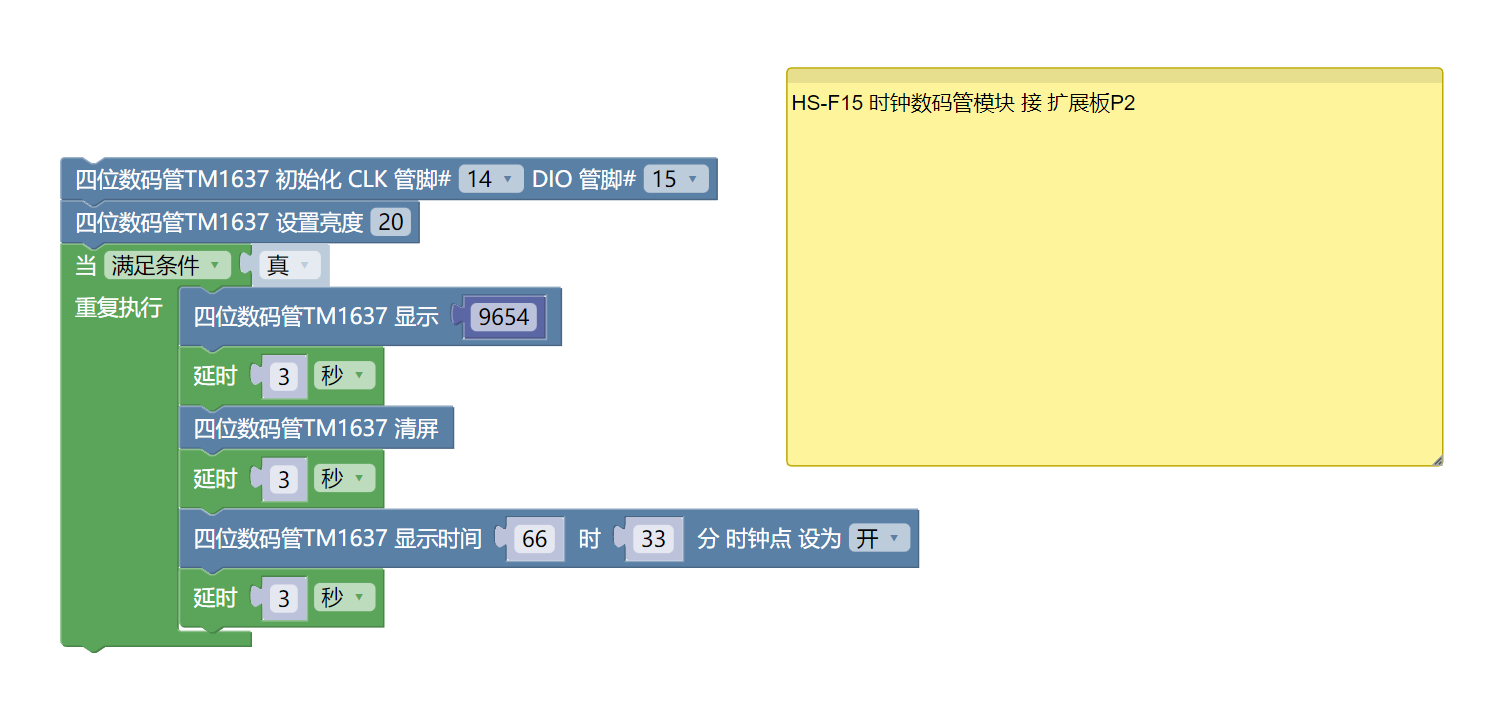
tm1637 = TM1637(clk=Pin(Pin(14)), dio=Pin(Pin(15)))
import time
tm1637.intensity(val=20)
while True:
tm1637.shownum(9654)
time.sleep(3)
tm1637.clear()
time.sleep(3)
tm1637.ShowTime(66,33,True)
time.sleep(3)
7, Mixly example program (graphical language)
Example program (UNO development board):Click to download
Attention: If prompted with an error message about the library file during program upload, please import the library file first!
Download and import tutorial of Mixly IDE Arduino library:Click to view
Example Program (ESP32 Development Board):Click to download
Attention: If prompted with an error message about the library file during program upload, please import the library file first!
Download and import tutorial for Mixly IDE ESP32 library:Click to view
8. Setting up the Test Environment
Arduino UNO Test Environment Setup
Prepare Components:
HELLO STEM UNO R3 DEVELOPMENT BOARD *1
HELLO STEM UNO EXP1 Expansion Board *1
USB TYPE-C DATA CABLE *1
TM637 4-digit clock display module (HS-F15A) *1
1P female to female Dupont wire *4 pieces or 2P female to female Dupont wire *2 pieces
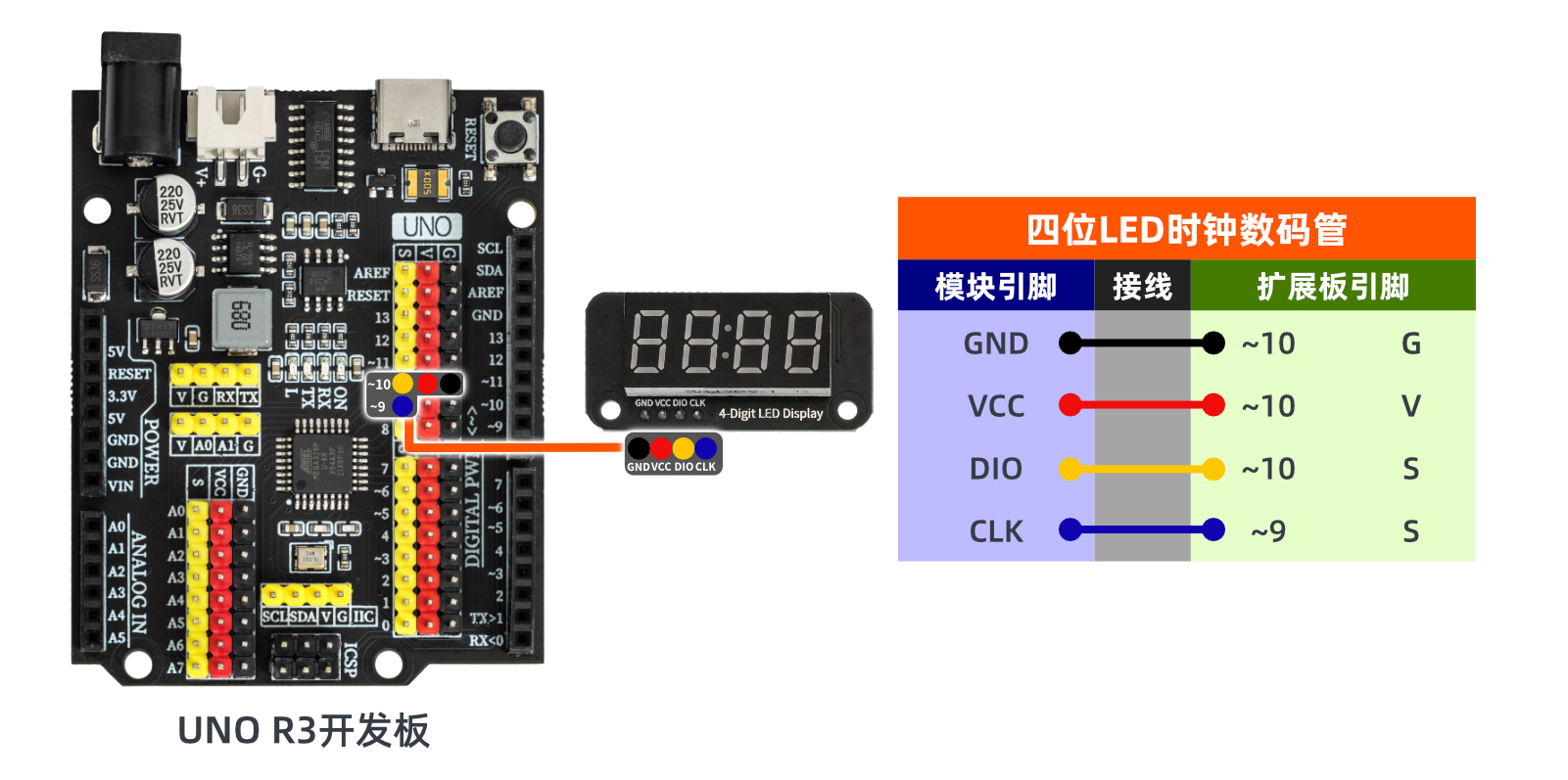
Circuit wiring diagram:
ESP32 Test Environment Setup
Prepare Components:Pending update...
Circuit wiring diagram:Pending update...
9, Video tutorial
Video tutorial:Click to view
10, Test results
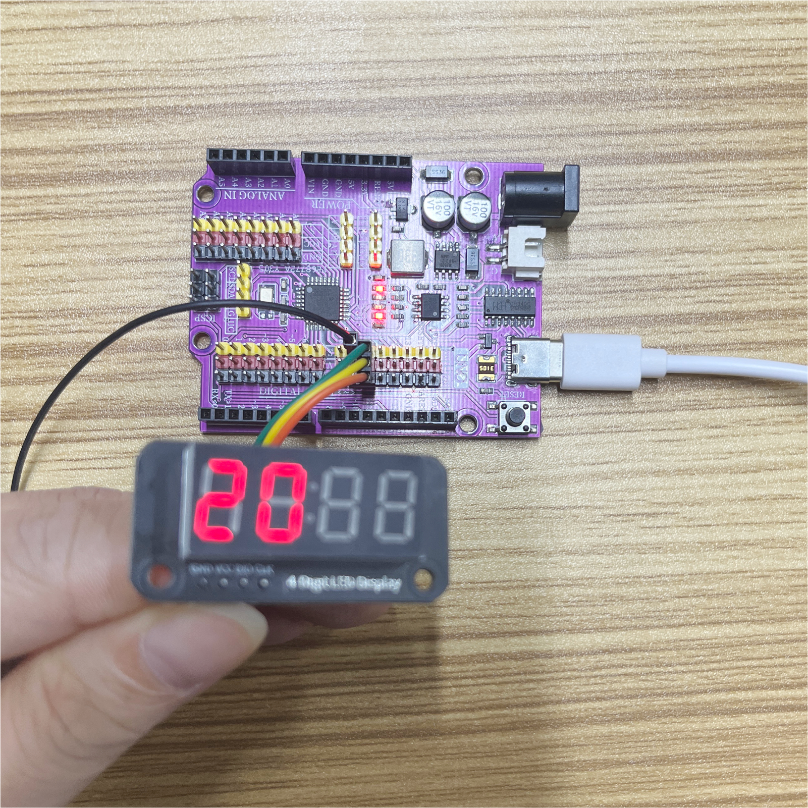
Arduino UNO test results:
After uploading the program to the Arduino UNO development board, you will see the seven-segment display start a 30-second countdown; at the same time, you will understand that a four-digit seven-segment display is equivalent to several LEDs lighting up and extinguishing to achieve the effect we want.
ESP32 Test Results:
Pending update...