
1. Introduction
Contactless IC cards, also known as radio frequency cards, are composed of IC chips and inductive antennas, encapsulated in a standard PVC card, with no exposed parts of the chip and antenna.It is a new technology that has developed in recent years, successfully combining radio frequency identification technology and IC card technology, ending the难题 of passive (no power in the card) and contactless, and is a major breakthrough in the field of electronic devices.The card is within a certain distance range (usually 5-10cm) close to the surface of the reader, and data read and write operations are completed through the transmission of radio waves.The working principle: The radio frequency reader sends a group of fixed-frequency electromagnetic waves to the IC card, and the card has an LC series resonant circuit, whose frequency is the same as that of the reader. Under the excitation of the electromagnetic wave, the LC resonant circuit produces resonance, so that there is charge in the capacitor; At the other end of this charge, there is a unidirectional conductive electron pump, which sends the charge in the capacitor to another capacitor for storage. When the accumulated charge reaches 2V, this capacitor can act as a power supply to provide working voltage for other circuits, to transmit the card data or receive the data from the reader.
The principle of transmission: Non-contact IC cards and readers complete read and write operations through radio waves.The communication frequency between them is 13.56MHZ.The contactless IC card itself is a passive card, when the reader performs read and write operations on the card, the signal emitted by the reader consists of two parts: one part is the power signal, which is received by the card and, together with its L/C, produces a momentary energy to supply the chip with power.The other part is the command and data signal, which commands the chip to complete data reading, modification, storage, and returns signals to the reader to complete a read and write operation.The reader is generally composed of a microcontroller, dedicated intelligent module, and antenna, and is equipped with communication interfaces, printing ports, I/O ports, etc., for application in various fields.
2. Schematic
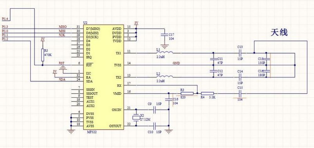
Module Parameters
Pin Name | description |
|---|---|
SDA | Serial data line |
SCK | SCK signal connected to MCU |
MOSI | MCU output, RC522 receive |
IRQ | Interrupt request output |
GND | Ground |
PST | Reset |
3.3V | Operating Voltage |
Supply voltage: 3.3V
Connection Type: 2.54mm Header
Installation method: Screw fixed
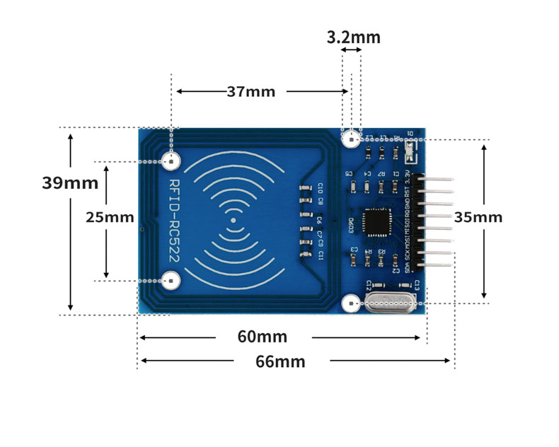
4, Circuit Board Size
5 of Arduino IDE example program
Attention: If prompted with an error message about the library file during program upload, please import the library file first!
Arduino IDE Library Download and Import Tutorial:Click to view
Example program (UNO development board):
#include <SPI.h>
#include <MFRC522.h>
#include <Servo.h>


String card[]={"83a08a34","83db1c13"};


String name[]={"YOU","I"};


MFRC522 rfid(10, 9);
String RFID_CardUID;
Servo servo_3;


String MFRC522_ReadCardUID(MFRC522 *_name){
  String _CardUID = "";
  for (byte _i = 0; _i < _name->uid.size; _i++){
    if(_name->uid.uidByte[_i] < 0x10)
      _CardUID += "0";
    _CardUID += String(_name->uid.uidByte[_i], HEX);
  }
  return _CardUID;
}


boolean MFRC522_IsNewCard(MFRC522 *_name){
  if(!_name->PICC_IsNewCardPresent())
    return false;
  if(!_name->PICC_ReadCardSerial())
    return false;
  return true;
}


void setup(){
  Serial.begin(9600);
  SPI.begin();
  rfid.PCD_Init();
  RFID_CardUID = "";
  servo_3.attach(3);
  Serial.println("读取RFID卡号测试");
  servo_3.write(90);
  delay(10);
}


void loop(){
  if(MFRC522_IsNewCard(&rfid)){
    RFID_CardUID = MFRC522_ReadCardUID(&rfid);
    Serial.println(String("Card UID:") + String(RFID_CardUID));
    for (int i = (0); i <= (sizeof(card)/sizeof(card[0])); i = i + (1)) {
      if (RFID_CardUID == card[i]) {
        Serial.println(name[i]);
        servo_3.write(179);
        delay(2000);


      }
      servo_3.write(90);
      delay(10);
    }
    rfid.PICC_HaltA();
    rfid.PCD_StopCrypto1();
  }
  delay(10);


}
6, ESP32 Python Example (for Mixly IDE/Misashi)
Choose the development board Python ESP32 [ESP32 Generic(4MB)] and upload in code mode
Attention: If prompted with an error message about the library file during program upload, please import the library file first!
Download and import tutorial for Mixly IDE ESP32 library:Click to view
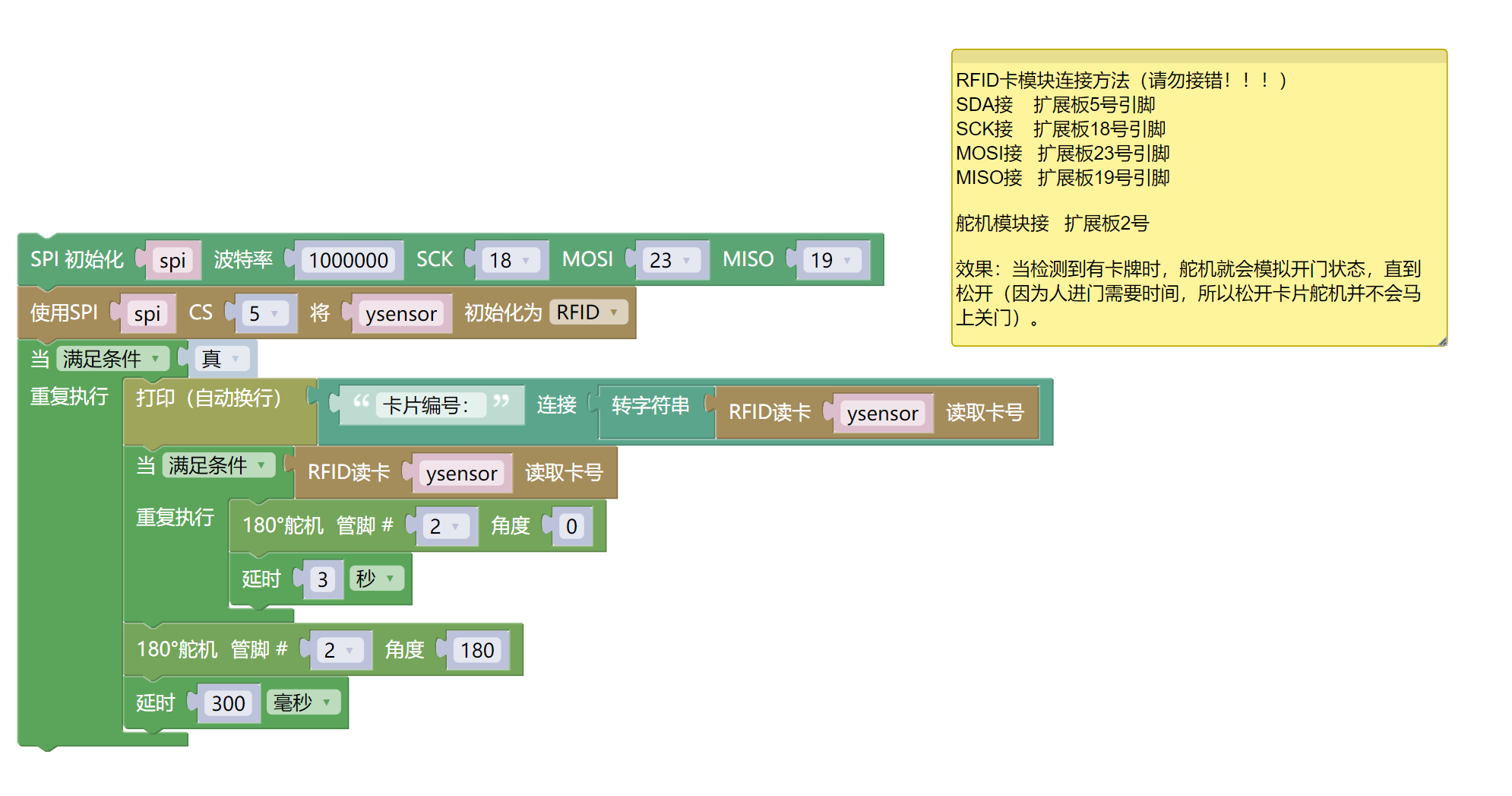
Example program (ESP32-Python):
import machine
import rc522
import servo
import time
spi = machine.SoftSPI(baudrate=1000000, sck=machine.Pin(18), mosi=machine.Pin(23), miso=machine.Pin(19))
ysensor = rc522.RC522(spi,5)
while True:
print(('卡片编号:' + str(ysensor.read_card(0, x="id"))))
while ysensor.read_card(0, x="id"):
servo.servo180_angle(2,0)
time.sleep(3)
servo.servo180_angle(2,180)
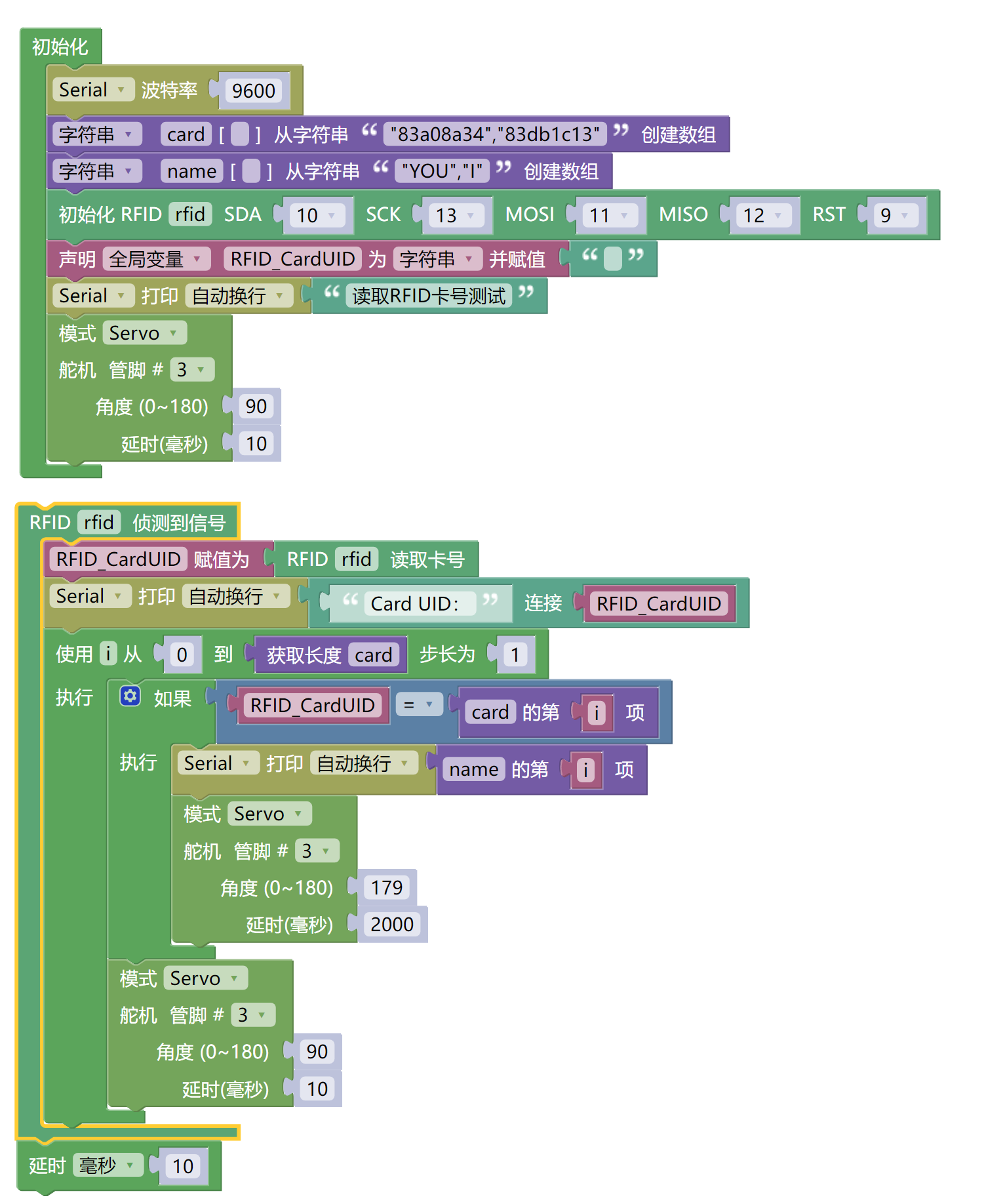
time.sleep_ms(300)7, Mixly example program (graphical language)
Example program (UNO development board):Click to download
Attention: If prompted with an error message about the library file during program upload, please import the library file first!
Download and import tutorial of Mixly IDE Arduino library:Click to view
Example Program (ESP32 Development Board):Click to download
Attention: If prompted with an error message about the library file during program upload, please import the library file first!
Download and import tutorial for Mixly IDE ESP32 library:Click to view
8. Setting up the Test Environment
Arduino UNO Test Environment Setup
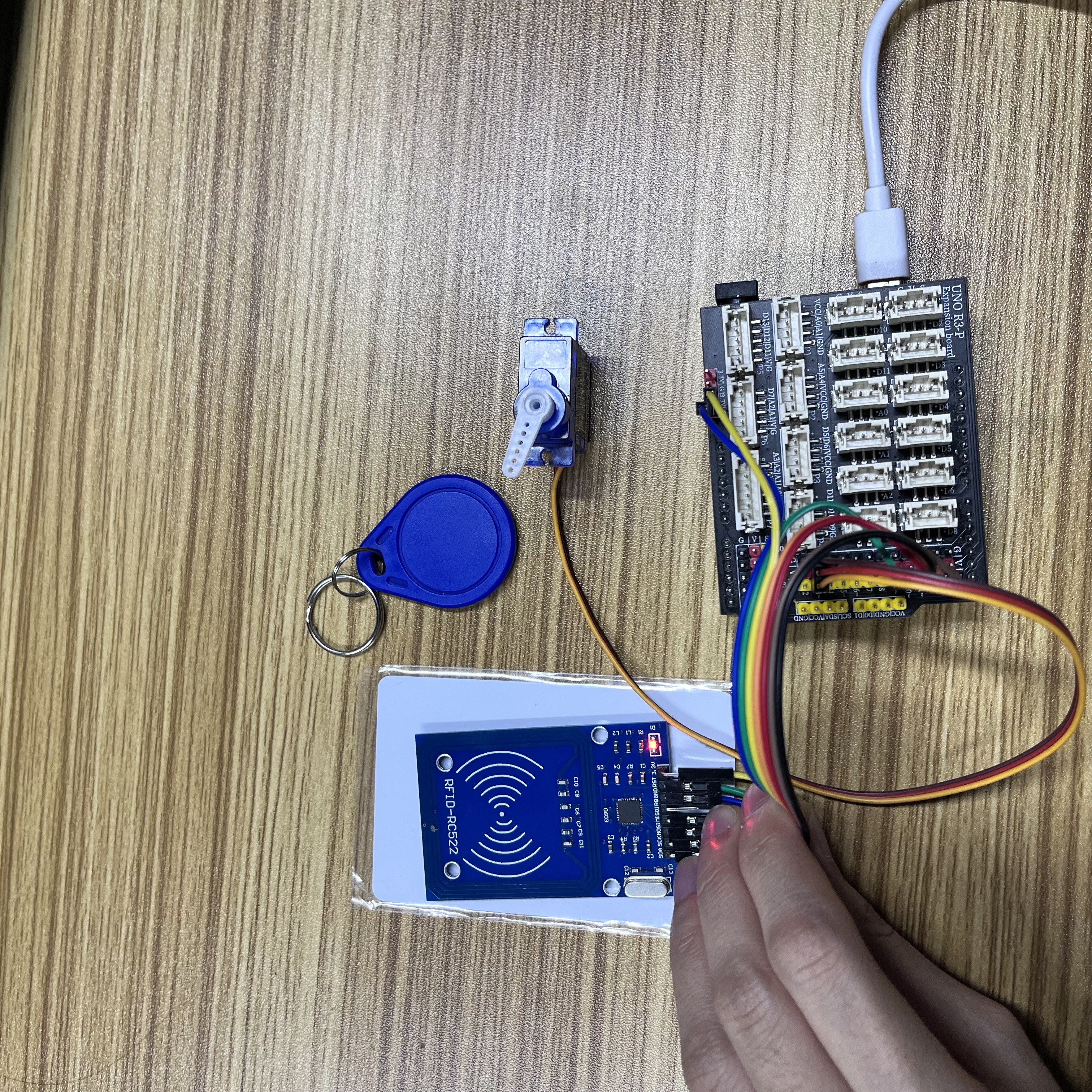
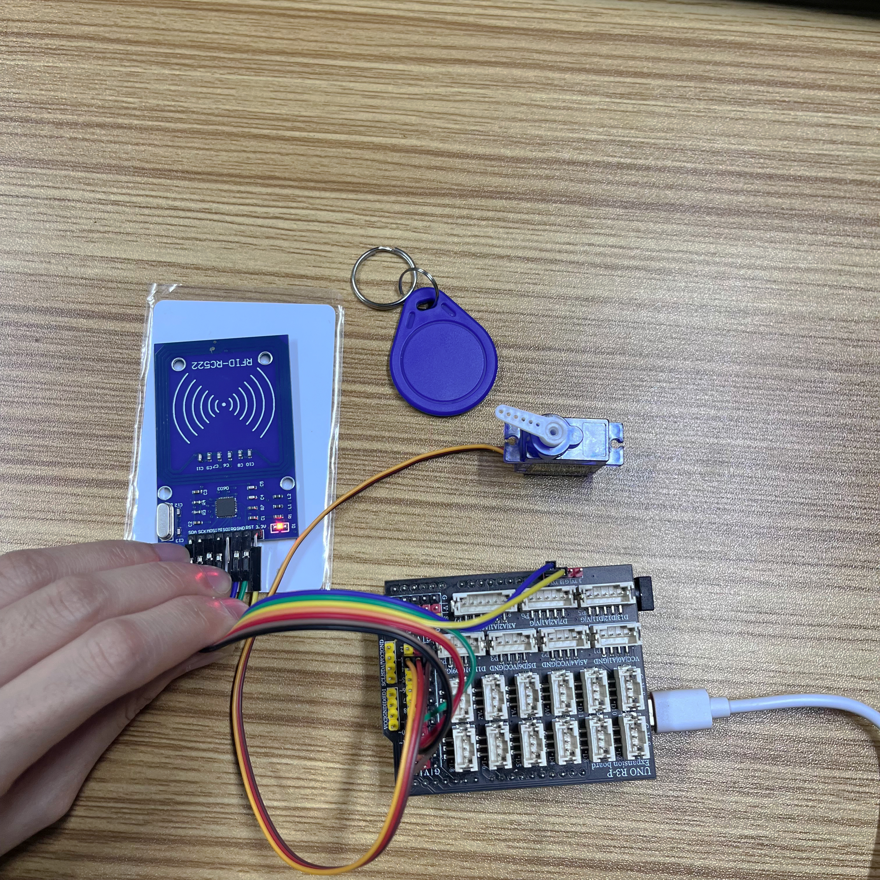
Prepare Components:
UNO-R3 Development Board*1
UNO-R3 P Expansion Board
USB TYPE-C DATA CABLE *1
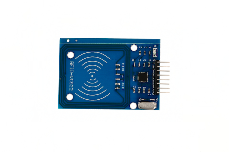
RFID-RC522 Radio Frequency IC Card Sensor Module*1
Blank Card*1
Special Shape Card*1
9g servo*1
1P female-to-female Dupont wire *7 pieces or 7P female-to-female Dupont wire *1 piece
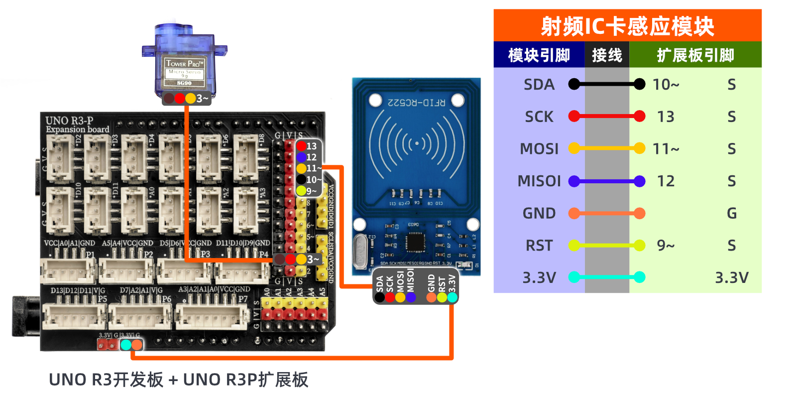
Circuit wiring diagram:
ESP32 Test Environment Setup
Prepare Components:Pending update...
Circuit wiring diagram:Pending update...
9, Video tutorial
Video tutorial:Click to view
10, Test results
Arduino UNO test results:
After connecting the device to the wire, after burning the above program to the Arduino UNO development board, the servo will rotate to simulate opening and closing the door after swiping the card.
ESP32 Test Results:
Pending update...