
1. Introduction
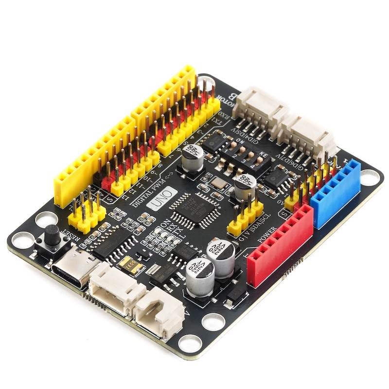
This Arduino development board is designed specifically for Lego enthusiasts and creators, it is compatible with Lego programming bricks and can be easily installed on Lego technology bricks and MOC bricks.Not only that, it also supports Lego battery power, making your creation more portable.
This development board is equipped with two motor drives, which can be controlled for forward and reverse rotation and speed through programming. The output power reaches up to 9V/2A, and the output interface is compatible with LEGO motor interfaces, perfectly supporting LEGO steering motors.In addition, the motor power output is equipped with a separate switch for easy control.
It also comes with a 2.54mm pitch GVS pin header expansion interface, allowing you to easily expand more sensor devices and add more features to your project.
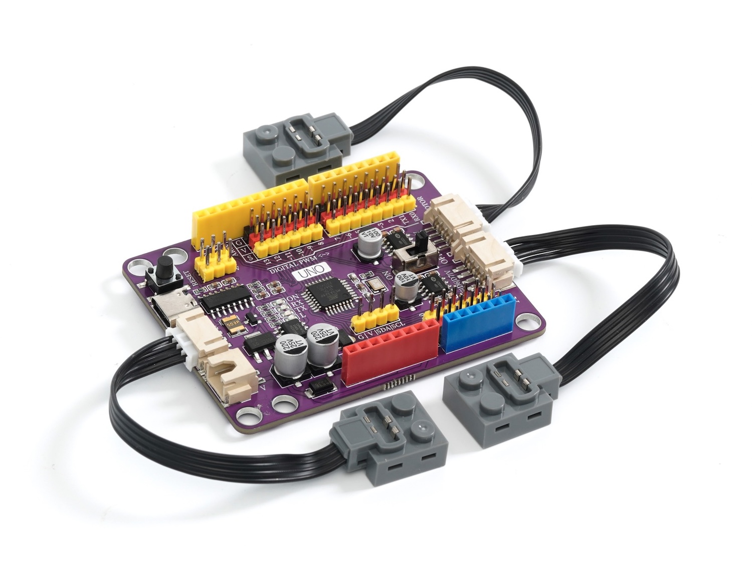
When used with the HS-UNO-EXP3 PH MOC expansion board, you can use the PH2.0 terminal line to connect the development board and the sensor with a single wire, simplifying the wiring process.
In short, this Arduino development board compatible with Lego programming bricks offers more possibilities for your Lego creations, allowing your imagination to be fully realized.Whether it is a robot project, smart building, or other creative works, it will become a powerful tool for you to realize your creativity.Come explore the infinite possibilities of the LEGO world!
2, Technical Specifications
Microcontroller: ATmega328P
Operating Voltage: 5V
Input Voltage (recommended): 6-9V
Digital input/output pins: 14 in total (of which 6 pins can be used as PWM pins)
PWM Pins: 6
Analog Input Pins: 6
Input/output pin DC current: 20 milliamperes
3.3V pin current: 500 milliamperes
Flash Memory (Flash memory): 32KB
SRAM (Static Random-Access Memory): 2KB
EEPROM: 1KB
Built-in LED pin: 13
Download interface: USB Type-C
Serial Port Controller: CH340C
Supported Programming IDEs: Arduino IED, Mixly, mblock, Scratch
3, Features
This is an Arduino development board compatible with Lego programming bricks, supporting installation on Lego technology bricks, MOC bricks.
The development board supports Lego battery power supply
Development board with dual motor drive, can be controlled by programming for forward and reverse rotation and speed, with output power of 9V/2A, compatible with LEGO motor interface, supports LEGO steering motors, with a separate switch to control motor power output.
An interface with a 2.54mm pitch G V S pin header for easy expansion of more sensor devices.
Pair with HS-UNO-EXP3 PH MOC expansion board, can use PH2.0 terminal lines, connect the development board and sensor with a single wire.
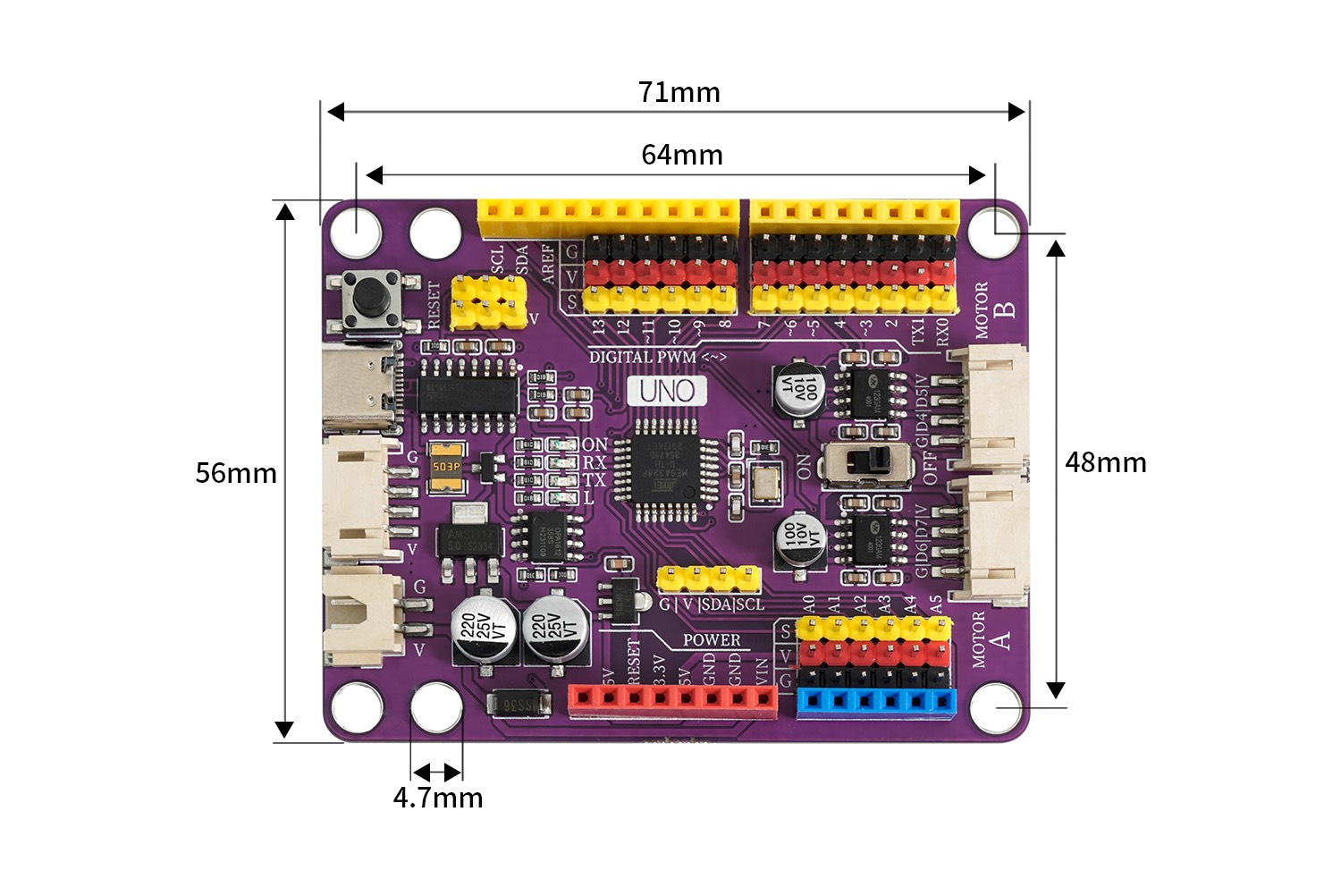
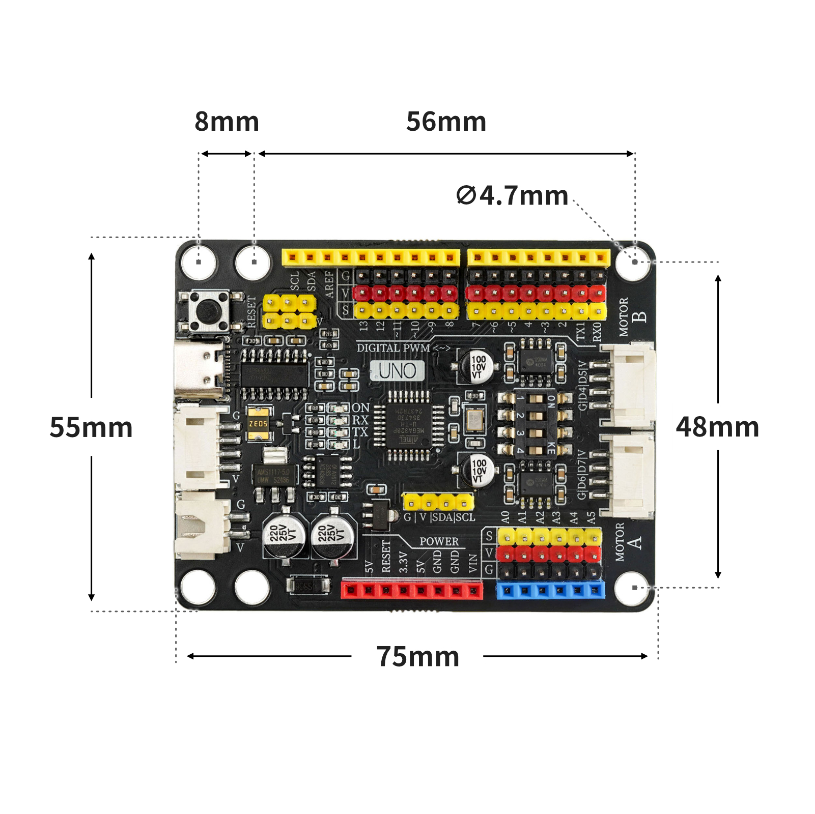
4, Circuit Board Size
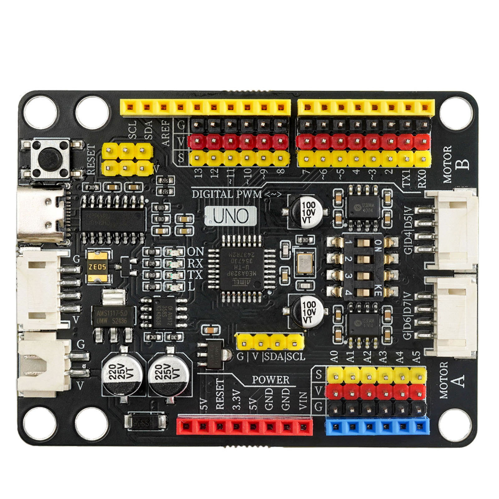
5, Development board decoding
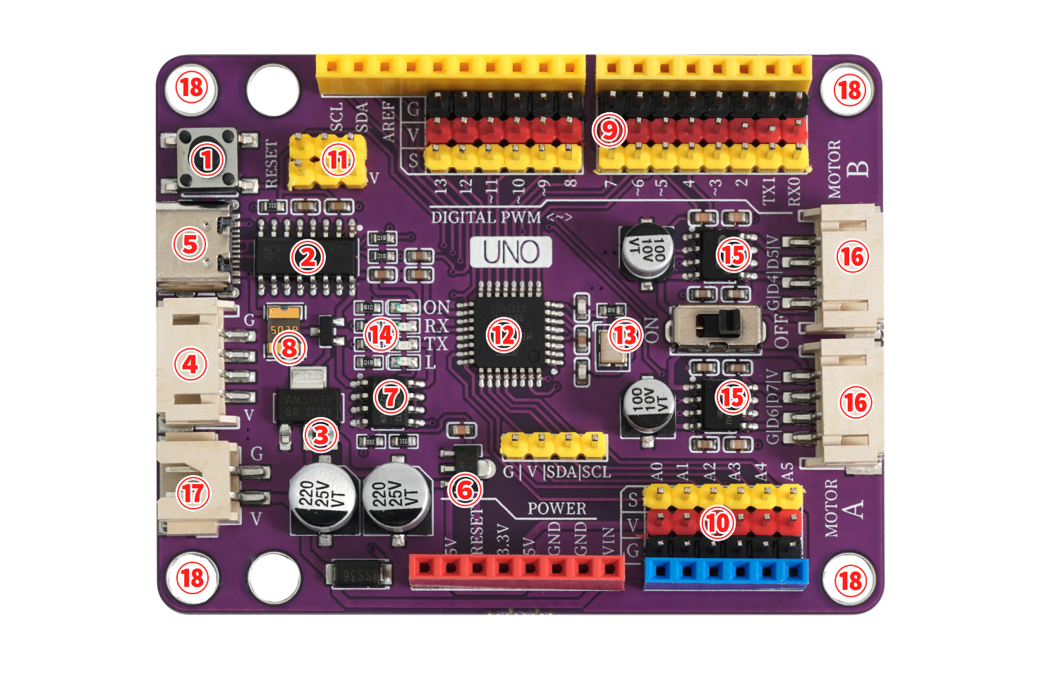
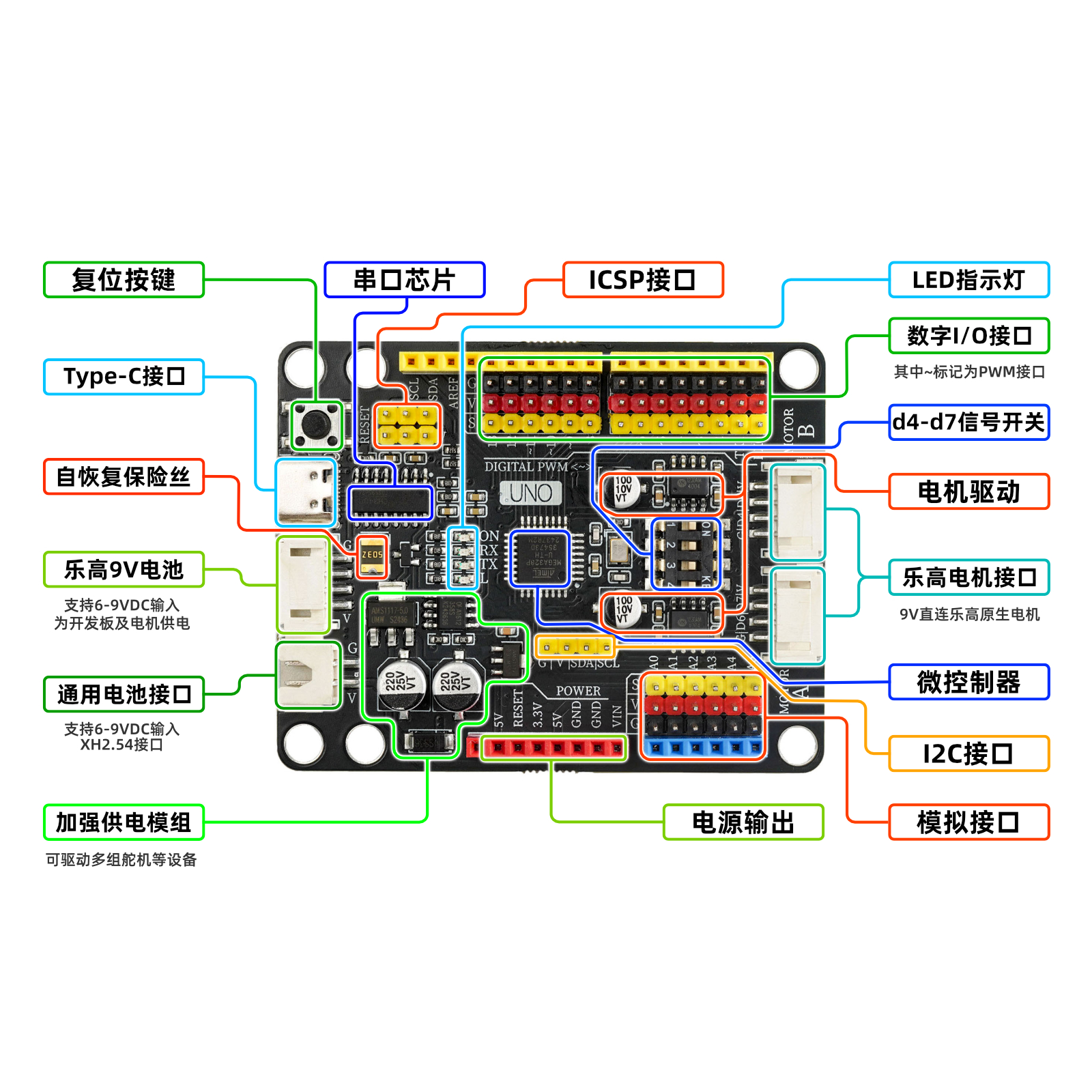
①Reset key
Press the reset button and run the program again.②USB serial chip
This chip is responsible for converting the data received from USB into serial data for the main control chip.③5V/1A power module
The power module is responsible for the power supply service of the motherboard, the 6-12V power supply from the external access is stepped down to 5V/2A/10W output, and can drive multiple servos, toy motors, miniature slides and other devices.④PH2.0 4P Power Interface (compatible with LEGO battery box)
This interface is compatible with the LEGO battery box wiring protocol, and can be connected to the LEGO battery box with the matching power adapter cable.The output voltage of this interface is 6-9V, depending on the input voltage you provide.⑤USB interface
USB Type-C interface, responsible for data download and USB power supply.⑥3.3V power chip
provides 3.3V voltage output for the development board.⑦Automatic switch controller for external and USB power supply
FDN340P field effect transistor + LMV358IDGKR amplifier composed of external power supply and USB power supply automatic switching control system.The development board is powered by USB interface by default. When an external power source is connected, the controller will automatically disconnect the USB power and switch to external power supply. After the external power source is disconnected, it will automatically switch back to USB power supply. This feature can protect the computer from the power interference of the development board's external power supply.⑧self-recovery fuse
When the development board is connected incorrectly, causing a short circuit, the fuse will automatically disconnect the circuit connection between the development board and the computer, thereby protecting the computer USB port from being burnt or the computer from crashing.⑨ Digital G|V|S Expansion Interface
The G|V|S interface is more convenient and quick to connect sensors or actuators, and no expansion board is needed when building a project either.G is the negative pole of GND power supply, V is the positive pole of VCC power supply, S is the IO signal interface, G/V provides an output power of 5V/2A, meeting the power supply requirements of most sensors and actuators.⑩ Simulated G|V|S Expansion Interface
The built-in simulation G|V|S expansion interface connects to the simulation sensor more conveniently and quickly, adding A6, A7 simulation input interfaces, and can connect more sensors.⑪ICSP serial data interface
Connect this interface when writing the initialization program to the development board or using the compiler to download the program.⑫ ATMEGA328P main control chip
The ATMEGA328P microcontroller is the brain of the development board, responsible for program storage, execution, calculation processing, signal input and output, and other functions.Crystal oscillator ⑬
Provide clock signal for ATMEGA328P microcontroller.LED indicator light
The board is equipped with 4 LED indicators, (ON) is the power indicator, it lights up when powered on, (RX)(TX) are serial port signal indicators, the LED lights blink when there is serial port communication, (L) is the D13 pin indicator light, the light is on when the D13 signal is high.⑮Motor, motor drive chip and drive switch
Mounted with two Drive chips, output power 9V | 2A, supports PMW speed regulation, a toggle switch is set in the middle of the drive chip to control whether the motor drive works.⑥Motor, electrical motor interface
The motor interface uses a PH2.0 4P terminal interface, the interface wiring is compatible with the Lego motor wiring, and the included adapter cable can be directly connected to the Lego motor.⑰XH2.54 power interface
This interface is mainly used to connect lithium battery-powered devices, with an input voltage of 6-9V.⑱Lego block mounting hole
Hole diameter is 4.7mm, fully compatible with Lego bricks.
Notice
The UNO MOC Driver 2.0 development board and UNO MOC Driver development board have no difference in performance, the only difference is that the toggle switch of the UNO MOC Driver development board can only control the switches of 2 Lego motor interfaces at the same time, while the UNO MOC Driver 2.0 development board can independently control 2 of the Lego motor interfaces, or turn them all on or off.
HELLO STEM UNO MOC Driver has a resettable polyfuse that can protect the computer's USB port from short circuit and overcurrent.If a current greater than 1A is applied to the USB port, the fuse will automatically disconnect until the short circuit or overload is removed.
6. Special Lego motor, motor interface
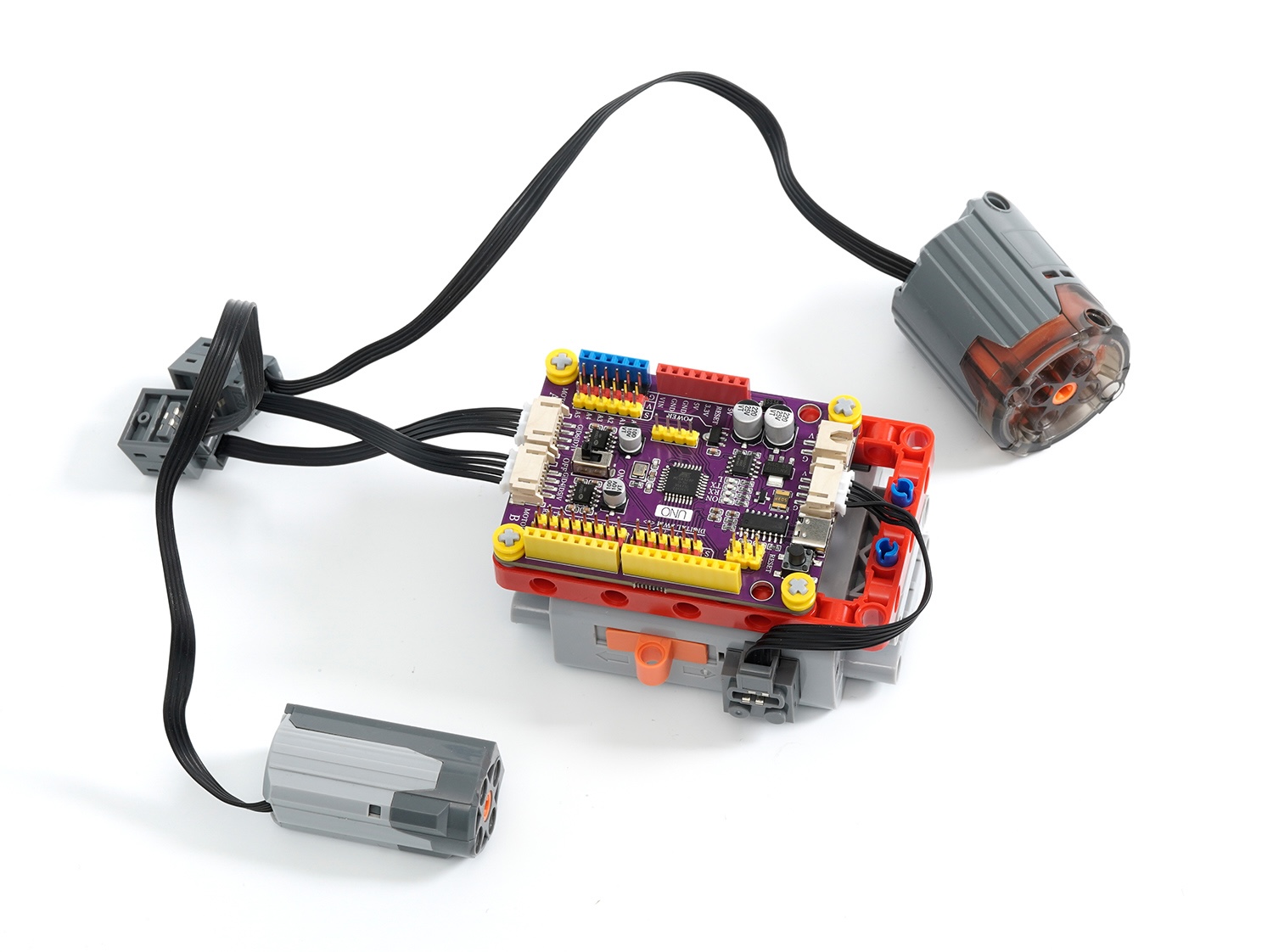
The motor interface uses a PH2.0 4P terminal interface, the interface wiring is compatible with the Lego motor wiring, and the included adapter cable can be directly connected to the Lego motor.
7, sensor and expansion accessories interface
The G|V|S interface built-in is more convenient and quick to connect sensors or actuators, and no expansion board is needed for project setup either.G/V provides an output power of 5V/2.5A, meeting the power supply needs of most sensors and actuators.
8. Add an expansion board
Install the expansion board, you can use the PH2.0 terminal line to connect the development board and sensor in one line, simplify the wiring process, and make it easier for beginners to get started.
9, download and install the driver
Download and installation method for USB drivers for Windows 7, 8, 10, 11 systems:Click to view
Download of USB drivers for Mac OS system:Download and install instructions for CH34X USB serial Mac OS driver
10, example setup and example program
1, onboard motor/motor driver test
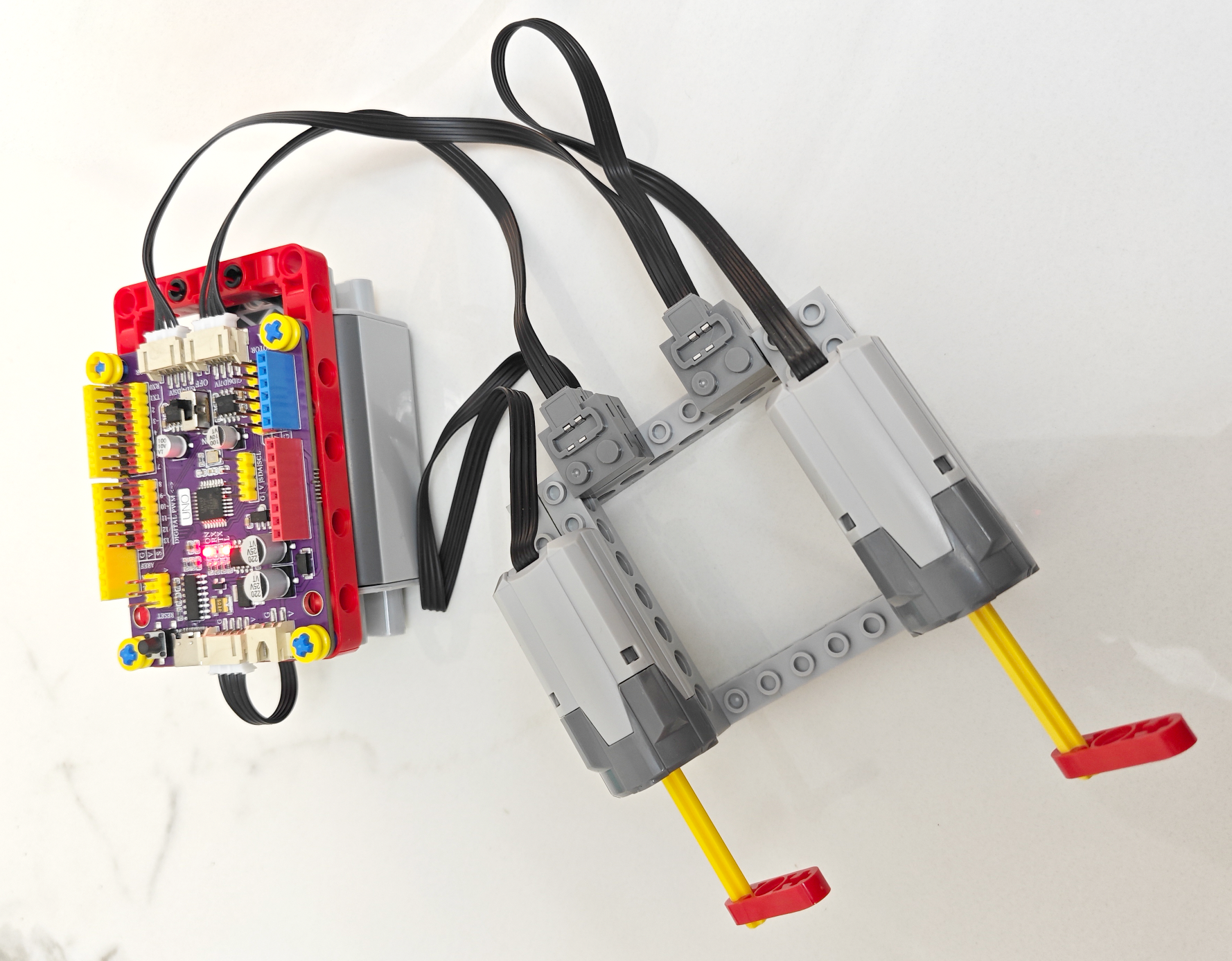
Note: The output of the LEGO 9686 battery box is 9V, the motor drive power is directly connected to the input end of the 9686 battery box, the motor drive voltage is consistent with the battery box voltage, so the on-board drive can only be connected to compatible LEGO motors/motors, and non-compatible LEGO motors may be damaged when powered on.
Due to the high power consumption of the LEGO motor, it is recommended to use Nanfu batteries, as other batteries may not work properly due to insufficient current.
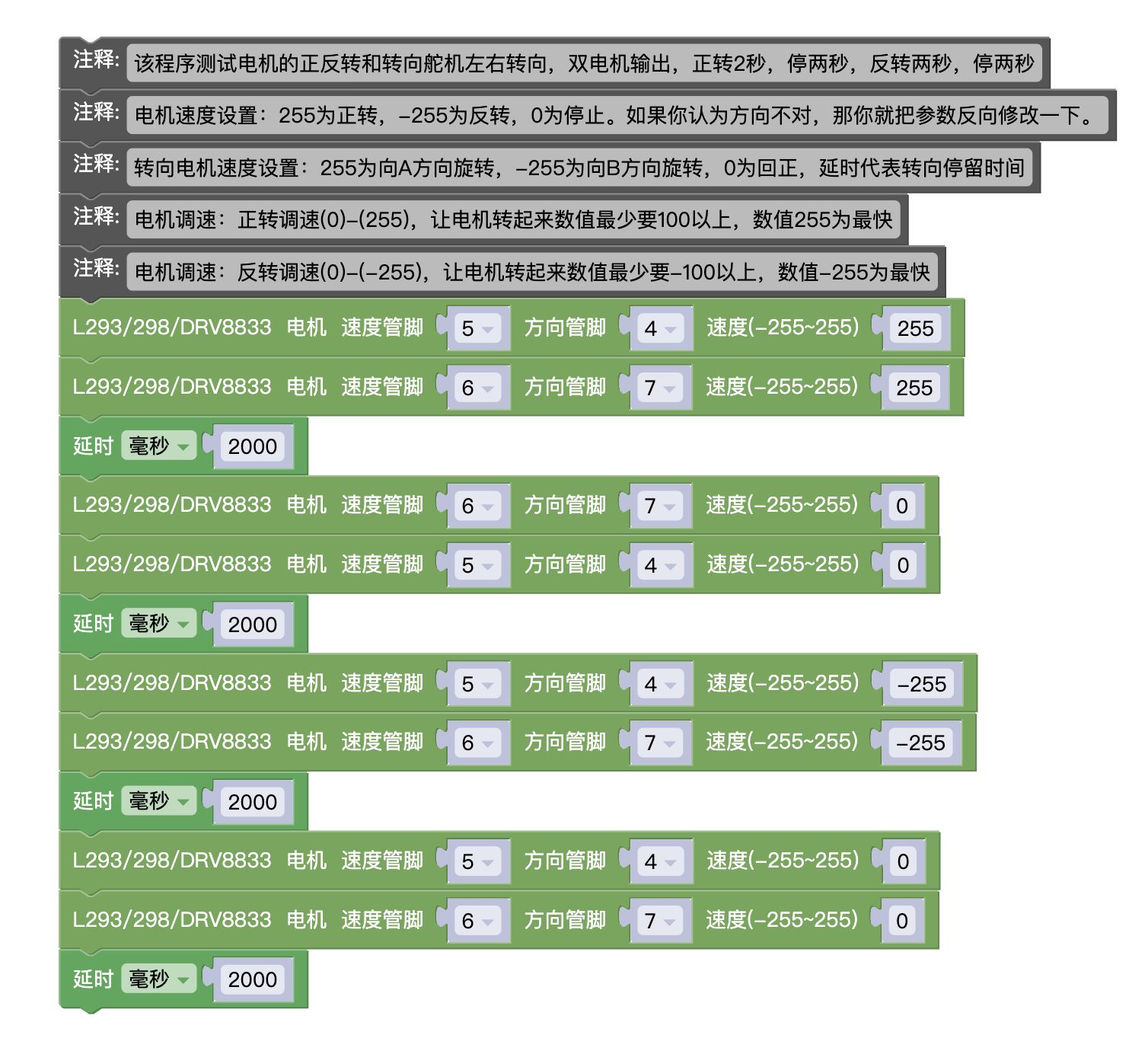
Mixly Mischii Test Program 1:Click to download
Note: 1. This program is suitable for testing steering motors and motors, as there is no braking program, and the rotational inertia of the motor will affect the accuracy of the rotation when testing the motor.
2, Encounter unstable development board situations, usually due to insufficient battery power, please set the speed value smaller, for example (200) or (-200)
Arduino IDE Test Program 1 (copy the following code and paste it into the IDE editor to upload)
Note: 1. This program is only suitable for testing M motor and steering motor, as there is no braking program added. The rotational inertia of the motor during testing will affect the accuracy of rotation.
2, Encounter unstable development board situations, usually due to insufficient battery power, please set the speed value smaller, for example (200) or (-200)
//该程序测试电机的正反转和转向舵机左右转向,双电机输出,正转2秒,停两秒,反转两秒,停两秒
//电机速度设置:255为正转,-255为反转,0为停止。如果你认为方向不对,那你就把参数反向修改一下。
//转向电机速度设置:255为向A方向旋转,-255为向B方向旋转,0为回正,延时代表转向停留时间
//电机调速:正转调速(0)-(255),让电机转起来数值最少要100以上,数值255为最快
//电机调速:反转调速(0)-(-255),让电机转起来数值最少要-100以上,数值-255为最快
void setMotor8833(int speedpin, int dirpin, int speed) {
if (speed == 0) {
digitalWrite(dirpin, LOW);
analogWrite(speedpin, 0);
} else if (speed > 0) {
digitalWrite(dirpin, LOW);
analogWrite(speedpin, speed);
} else {
digitalWrite(dirpin, HIGH);
analogWrite(speedpin, 255 + speed);
}
}
void setup(){
pinMode(5, OUTPUT);
pinMode(4, OUTPUT);
digitalWrite(5, LOW);
digitalWrite(4, LOW);
pinMode(6, OUTPUT);
pinMode(7, OUTPUT);
digitalWrite(6, LOW);
digitalWrite(7, LOW);
}
void loop(){
setMotor8833(5, 4, 255);
setMotor8833(6, 7, 255);
delay(2000);
setMotor8833(6, 7, 0);
setMotor8833(5, 4, 0);
delay(2000);
setMotor8833(5, 4, -255);
setMotor8833(6, 7, -255);
delay(2000);
setMotor8833(5, 4, 0);
setMotor8833(6, 7, 0);
delay(2000);
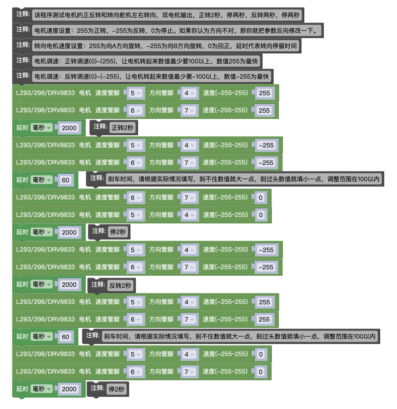
}Mixly Mixly test program 2:Click to download
Note: 1. This program is dedicated to testing motors, applicable to M, L, XL motor testing, and the braking time should be adjusted according to the actual situation during testing
2, Encounter unstable development board situations, usually due to insufficient battery power, please set the speed value smaller, for example (200) or (-200)
Arduino IDE Test Program 2 (copy the following code and paste it into the IDE editor to upload)
Note: 1, This program is specifically used for testing motors, applicable to M, L, XL motor testing, and the braking time should be adjusted according to the actual situation during testing
2, Encounter unstable development board situations, usually due to insufficient battery power, please set the speed value smaller, for example (200) or (-200)
void setMotor8833(int speedpin, int dirpin, int speed) {
if (speed == 0) {
digitalWrite(dirpin, LOW);
analogWrite(speedpin, 0);
} else if (speed > 0) {
digitalWrite(dirpin, LOW);
analogWrite(speedpin, speed);
} else {
digitalWrite(dirpin, HIGH);
analogWrite(speedpin, 255 + speed);
}
}

void setup(){
pinMode(5, OUTPUT);
pinMode(4, OUTPUT);
digitalWrite(5, LOW);
digitalWrite(4, LOW);
pinMode(6, OUTPUT);
pinMode(7, OUTPUT);
digitalWrite(6, LOW);
digitalWrite(7, LOW);
}

void loop(){
setMotor8833(5, 4, 255);
setMotor8833(6, 7, 255);
delay(2000);
setMotor8833(5, 4, -255);
setMotor8833(6, 7, -255);
delay(60); //刹车时间
setMotor8833(6, 7, 0);
setMotor8833(5, 4, 0);
delay(2000);
setMotor8833(5, 4, -255);
setMotor8833(6, 7, -255);
delay(2000);
setMotor8833(5, 4, 255);
setMotor8833(6, 7, 255);
delay(60); //刹车时间
setMotor8833(5, 4, 0);
setMotor8833(6, 7, 0);
delay(2000);
}