1. Introduction
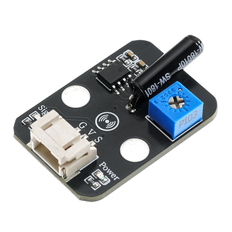
A vibration sensor is a sensor module designed based on the principle of spring oscillation.It can detect vibration signals and then output switch signals to Arduino. When the product is not vibrating, the vibration switch is in the open state, the output terminal outputs a high level, and the blue indicator light is not lit; when the product is vibrating, the vibration switch conducts instantaneously, the output terminal outputs a low level, and the blue indicator light is on; the module uses the PH2.0 interface and can be easily connected to the sensor expansion board with a digital connection line.It can perceive weak vibration signals and can realize interactive works related to vibration.Used for various vibration triggering functions, alarm reporting, smart cars, electronic bricks, etc.
2. Schematic
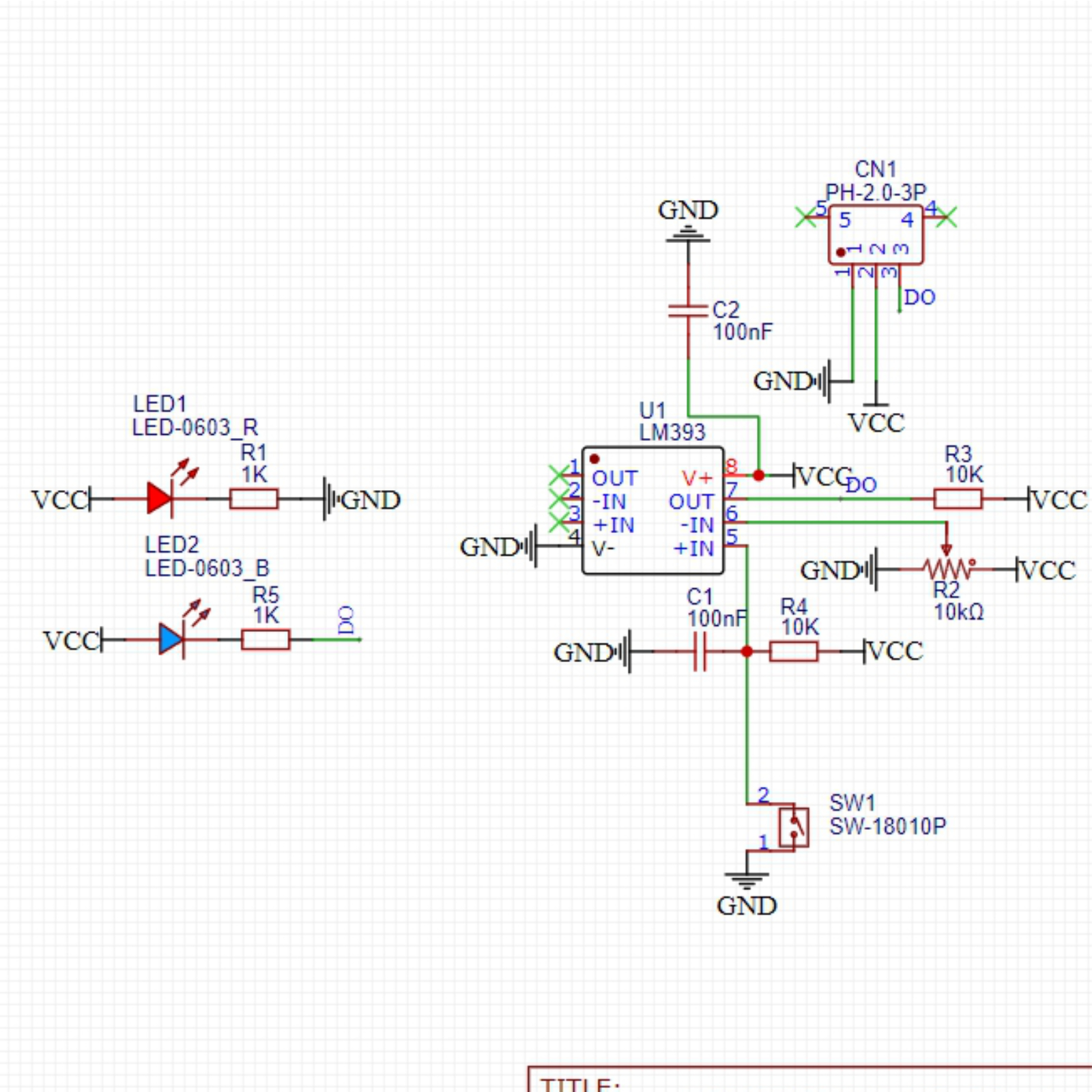
Module Parameters
Pin Name | description |
|---|---|
G | GND (Power Input) |
V | VCC (power positive terminal) |
S | Digital Signal Pin |
Power Supply Voltage: 3.3V / 5V
Connection method: PH2.0 3P terminal
Installation method: Lego assembly
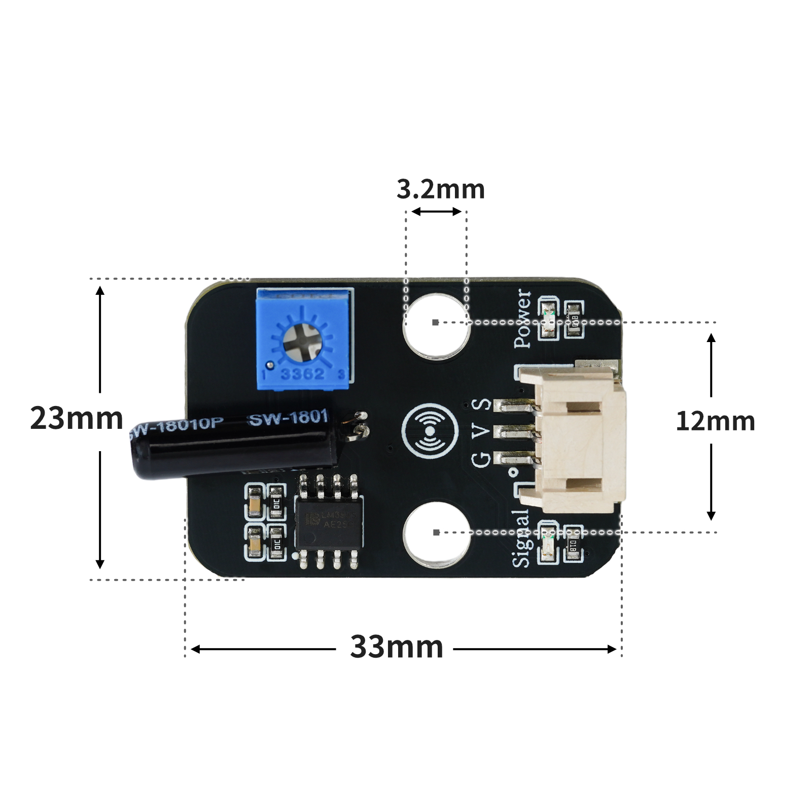
4, Circuit Board Size
5 of Arduino IDE example program
Example program (UNO development board):Click to download
void setup(){
  Serial.begin(9600);
  pinMode(A0, INPUT);
  pinMode(4, OUTPUT);
}

void loop(){
  //A0接敲击传感器,D4接led灯,晃动敲击传感器,led闪烁。
  if (digitalRead(A0) == 1) {
    Serial.println("未检测到冲击");
    digitalWrite(4,LOW);

  } else if (digitalRead(A0) == 0) {
    delay(300);
    digitalWrite(4,HIGH);
    Serial.println("传感器检测到冲击");
  }

}
Example Program (ESP32 Development Board — Based on Python language, cannot be uploaded using Arduino IDE):
import machine
import time
pin2 = machine.Pin(2, machine.Pin.IN)
pin4 = machine.Pin(4, machine.Pin.OUT)
while True:
if pin2.value() == 1:
pin4.value(0)
print('未检测到冲击')
else:
pin4.value(1)
print('传感器检测到冲击')
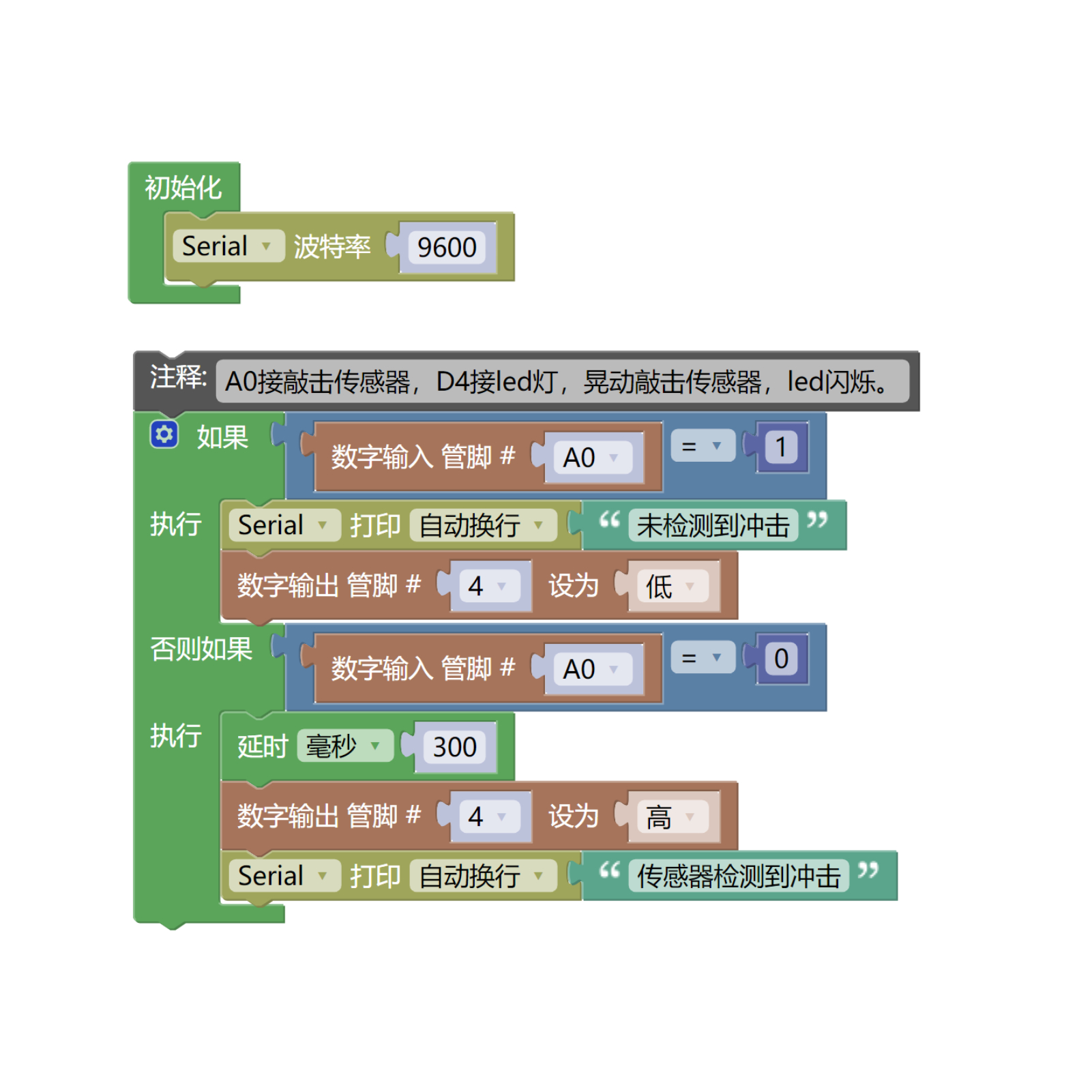
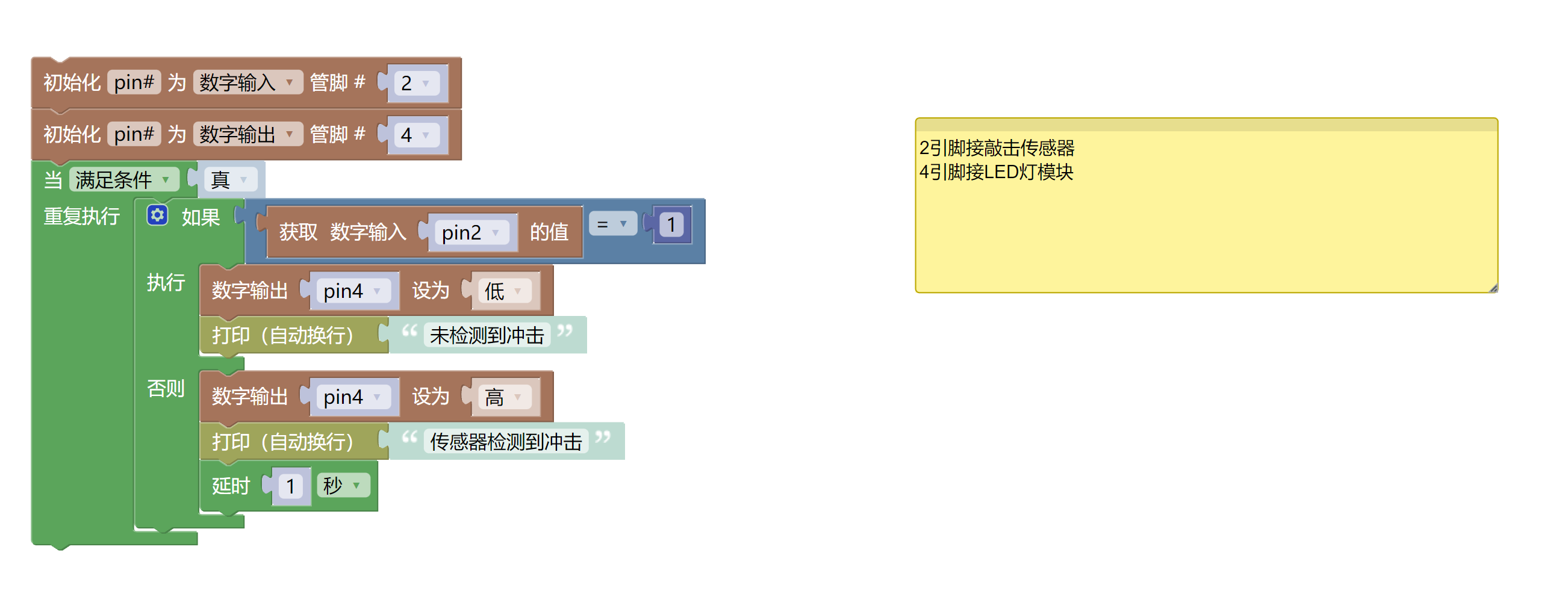
time.sleep(1)6, Miciqi Mixly Example Program (Graphical Language)
Example program (UNO development board):Click to download
Example Program (ESP32 Development Board):Click to download
7, Test Environment Setup
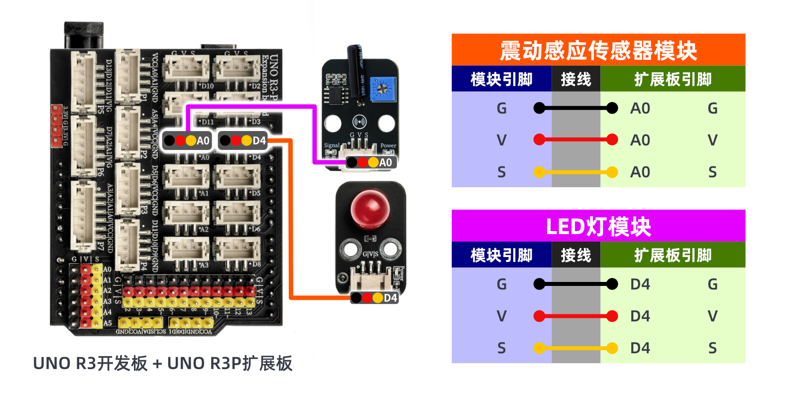
Arduino UNO Test Environment Setup
Prepare Components:
HELLO STEM UNO R3 PRO DEVELOPMENT BOARD *1
R3P expansion board *1
USB TYPE-C DATA CABLE *1
Tapping Sensor (HS-S61-L) *1
LED light module (HS-F08P) *1
PH2.0 3P double-ended terminal line *2 or PH2.0 3P connector to DuPont wire *2
Circuit wiring diagram:
Set up Micropython environment
Prepare Components:
Circuit wiring diagram:
8. Video tutorial
Video tutorial: Click to view
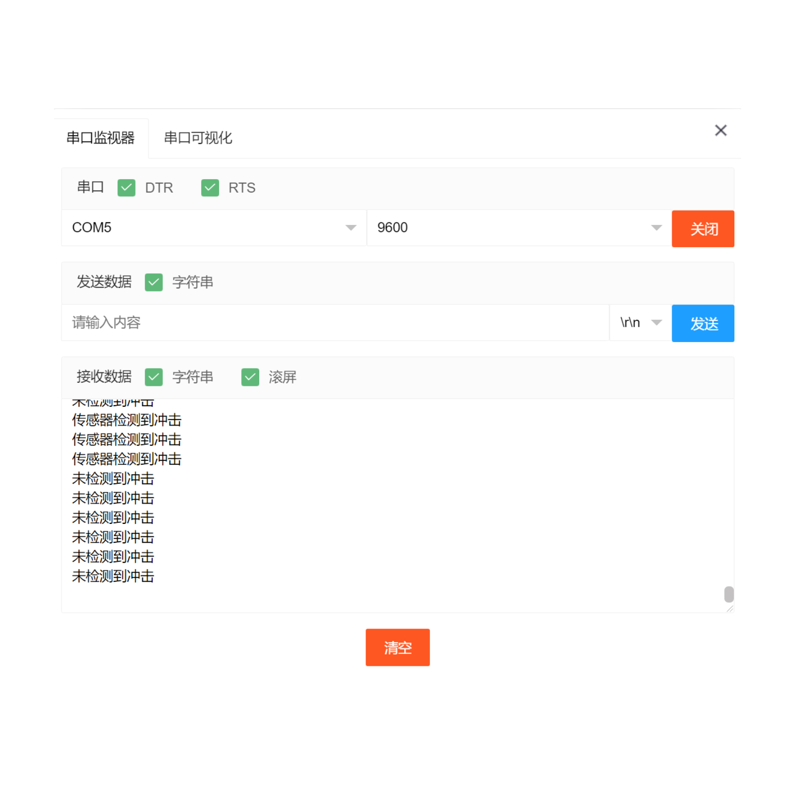
9. Test conclusion
After the device is connected to the wire, burn the above program to the UNO-R3 PRO development board, and then connect the power supply.Open the serial port monitor, set the baud rate to 9600.When the sensor detects an impact signal, the input is low level (0), and the LED flashes and illuminates; otherwise, the LED extinguishes.