1. Introduction
Implement motor control: Connect to an external microcontroller via the I2C interface, use the PCA9685 chip to output PWM signals, and control the speed and other parameters of the four-channel MOC PF motor.8PIN Interface: Provides 8 pin interfaces, which can be used to connect sensors, other controllers, or expand more functions, facilitating further expansion and integration of the system.
Power management: It usually integrates power interfaces to provide the appropriate power for the connected motors and the chips themselves.Part of the expansion board also has reverse connection protection circuit, preventing damage to the circuit due to reversed positive and negative poles of the power supply.
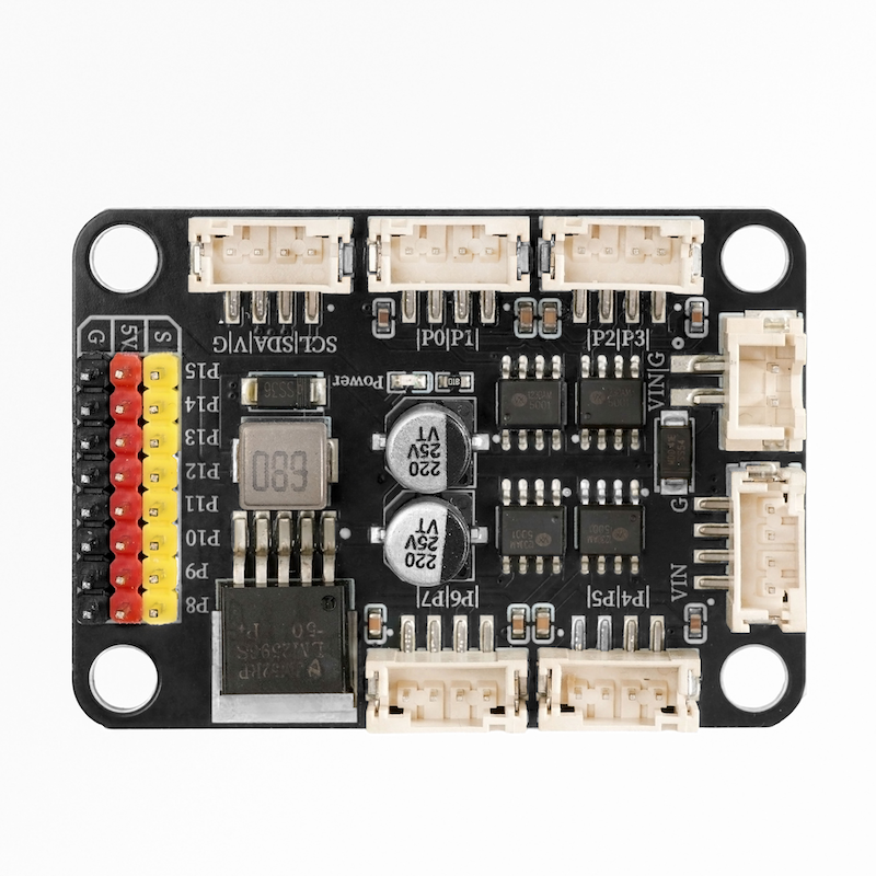
2. Schematic
Module Parameters
Pin Name | description |
|---|---|
G | GND (Negative Power Input) |
V | VCC (Positive Power Input) |
SDA | Data pin |
SCL | clock pin |
Supply voltage: 3.3V-5V
Connection method: PH2.0 4P terminal wire
Installation method: Lego assembly
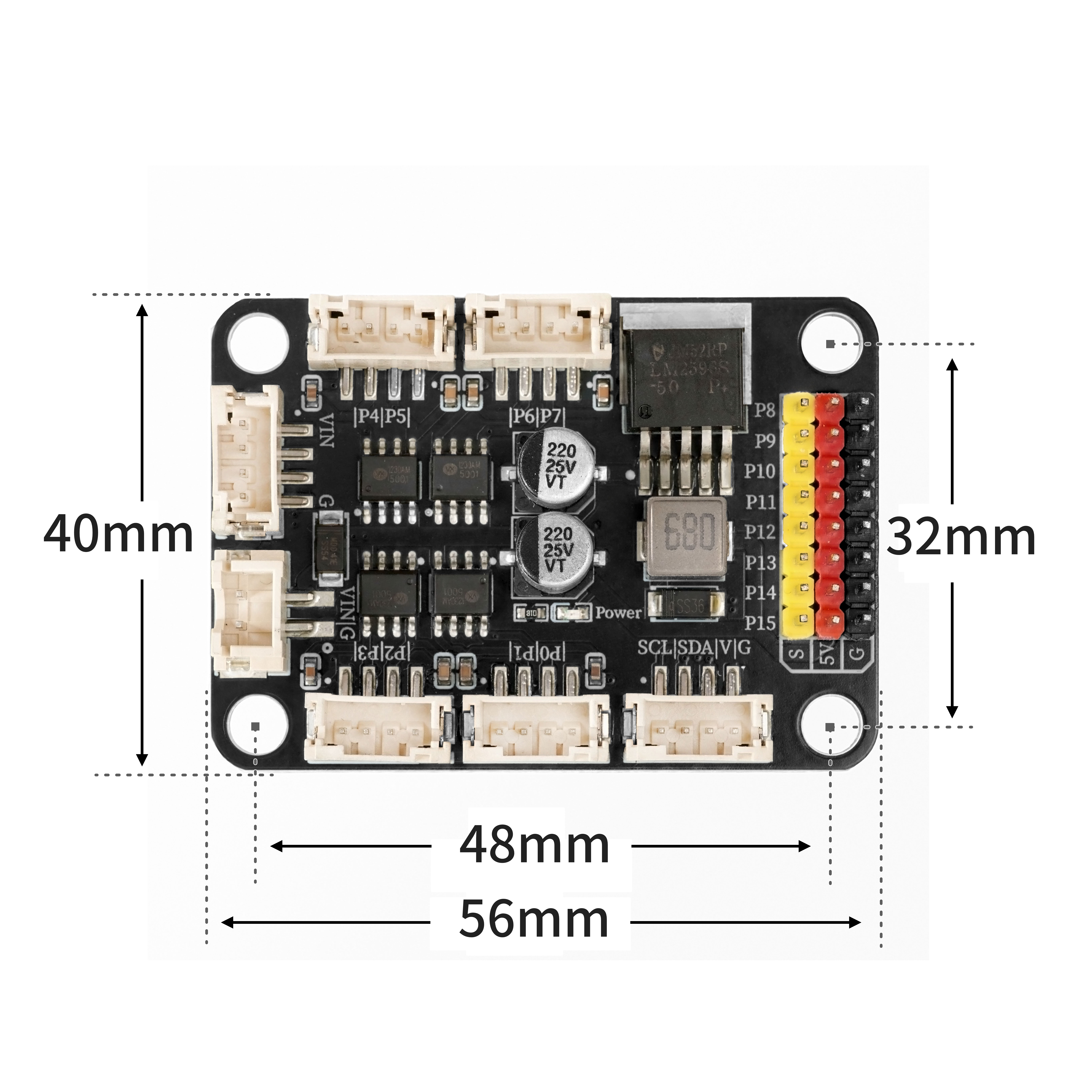
4, Circuit Board Size
Add Arduino Library File
Arduino library file installation steps:Reference link
Arduino library file: Click to download
Installation steps for the MiQi UNO development board library (download and install the MiQi library before using the code):Reference link
6, Add MicroPython environment library file
MiXin ESP32 development board library download and installation steps (download and install the MiXin library before using the code):Reference link
7. Arduino IDE example program
Example Program (UNO Development Board): Click to Download
#include "Wire.h"
#include "Adafruit_PWMServoDriver.h"
Adafruit_PWMServoDriver PWM = Adafruit_PWMServoDriver(0x40);

void setup(){
  PWM.begin();
  PWM.setPWMFreq(85);
}

void loop(){
  PWM.setPWM(0,0,0);
  PWM.setPWM(1,0,2048);
  PWM.setPWM(2,0,0);
  PWM.setPWM(3,0,2048);
  PWM.setPWM(4,0,0);
  PWM.setPWM(5,0,2048);
  PWM.setPWM(6,0,0);
  PWM.setPWM(7,0,2048);
  for (int i = 0; i <= 180; i = i + (1)) {
    PWM.setPWM(8,0,(map(i, 0, 180, 140, 680)));
    PWM.setPWM(9,0,(map(i, 0, 180, 140, 680)));
    PWM.setPWM(10,0,(map(i, 0, 180, 140, 680)));
    PWM.setPWM(11,0,(map(i, 0, 180, 140, 680)));
    delay(50);
  }

}
Example Program (ESP32 Development Board):
from machine import I2C, Pin
import time
from mixpy import math_map


PCA9685_MODE1      = 0x00
PCA9685_MODE2      = 0x01
PCA9685_LED0_ON_L  = 0x06
PCA9685_LED0_ON_H  = 0x07
PCA9685_LED0_OFF_L = 0x08
PCA9685_LED0_OFF_H = 0x09
PCA9685_ALLLED_ON_L  = 0xFA
PCA9685_ALLLED_ON_H  = 0xFB
PCA9685_ALLLED_OFF_L = 0xFC
PCA9685_ALLLED_OFF_H = 0xFD
PCA9685_PRESCALE     = 0xFE

MODE1_ALLCAL  = 0x01
MODE1_SUB3    = 0x02
MODE1_SUB2    = 0x04
MODE1_SUB1    = 0x08
MODE1_SLEEP   = 0x10
MODE1_AI      = 0x20
MODE1_EXTCLK  = 0x40
MODE1_RESTART = 0x80

MODE2_OUTNE_0 = 0x01
MODE2_OUTNE_1 = 0x02
MODE2_OUTDRV  = 0x04
MODE2_OCH     = 0x08
MODE2_INVRT   = 0x10


PCA9685_I2C_ADDRESS       = 0x40
FREQUENCY_OSCILLATOR_HZ   = 25_000_000
PRESCALE_MIN = 3
PRESCALE_MAX = 255


class PCA9685:
    def __init__(self, i2c: I2C, addr: int = PCA9685_I2C_ADDRESS):
        self.i2c = i2c
        self.addr = addr
        self._oscillator_freq = FREQUENCY_OSCILLATOR_HZ

    def _write8(self, reg: int, val: int):
        self.i2c.writeto_mem(self.addr, reg, bytes([val & 0xFF]))

    def _read8(self, reg: int) -> int:
        return self.i2c.readfrom_mem(self.addr, reg, 1)[0]

    def _write4(self, base_reg: int, on: int, off: int):
        buf = bytearray(4)
        buf[0] = on & 0xFF
        buf[1] = (on >> 8) & 0x0F
        buf[2] = off & 0xFF
        buf[3] = (off >> 8) & 0x0F
        self.i2c.writeto_mem(self.addr, base_reg, buf)

    def begin(self):
        self.reset()
        mode1 = self._read8(PCA9685_MODE1)
        self._write8(PCA9685_MODE1, mode1 | MODE1_AI)
        self.set_output_mode(True)

    def reset(self):
        self._write8(PCA9685_MODE1, MODE1_RESTART)  # 写 RESTART
        time.sleep_ms(10)

    def sleep(self):
        m1 = self._read8(PCA9685_MODE1)
        self._write8(PCA9685_MODE1, m1 | MODE1_SLEEP)
        time.sleep_ms(5)

    def wakeup(self):
        m1 = self._read8(PCA9685_MODE1)
        self._write8(PCA9685_MODE1, m1 & (~MODE1_SLEEP))
        time.sleep_ms(5)

    def set_output_mode(self, totempole: bool = True):
        m2 = self._read8(PCA9685_MODE2)
        if totempole:
            m2 |= MODE2_OUTDRV
        else:
            m2 &= ~MODE2_OUTDRV
        self._write8(PCA9685_MODE2, m2)

    def set_oscillator_frequency(self, freq_hz: int):
        self._oscillator_freq = int(freq_hz)

    def get_oscillator_frequency(self) -> int:
        return self._oscillator_freq

    def set_pwm_freq(self, freq_hz: float):
        if freq_hz < 1.0:
            freq_hz = 1.0
        if freq_hz > 3500.0:
            freq_hz = 3500.0

        prescaleval = ((self._oscillator_freq / (freq_hz * 4096.0)) + 0.5) - 1.0
        if prescaleval < PRESCALE_MIN:
            prescaleval = PRESCALE_MIN
        if prescaleval > PRESCALE_MAX:
            prescaleval = PRESCALE_MAX
        prescale = int(prescaleval)

        oldmode = self._read8(PCA9685_MODE1)
        newmode = (oldmode & ~MODE1_RESTART) | MODE1_SLEEP
        self._write8(PCA9685_MODE1, newmode)
        self._write8(PCA9685_PRESCALE, prescale)
        self._write8(PCA9685_MODE1, oldmode)
        time.sleep_ms(5)
        self._write8(PCA9685_MODE1, oldmode | MODE1_RESTART | MODE1_AI)

    def read_prescale(self) -> int:
        return self._read8(PCA9685_PRESCALE)

    def set_pwm(self, ch: int, on: int, off: int):
        base = PCA9685_LED0_ON_L + 4 * ch
        self._write4(base, on & 0x1FFF, off & 0x1FFF)

    def set_pin(self, ch: int, val: int, invert: bool = False):
        if val < 0:
            val = 0
        if val > 4095:
            val = 4095

        if invert:
            if val == 0:
                self.set_pwm(ch, 4096, 0)   # fully ON
            elif val == 4095:
                self.set_pwm(ch, 0, 4096)  # fully OFF
            else:
                self.set_pwm(ch, 0, 4095 - val)
        else:
            if val == 4095:
                self.set_pwm(ch, 4096, 0)  # fully ON
            elif val == 0:
                self.set_pwm(ch, 0, 4096)  # fully OFF
            else:
                self.set_pwm(ch, 0, val)

    def write_microseconds(self, ch: int, us: int):
        prescale = self.read_prescale() + 1
        us_per_bit = (1_000_000.0 * prescale) / float(self._oscillator_freq)
        ticks = int(us / us_per_bit + 0.5)
        if ticks < 0:
            ticks = 0
        if ticks > 4095:
            ticks = 4095
        self.set_pwm(ch, 0, ticks)


i2c = I2C(0, scl=Pin(22), sda=Pin(21), freq=400000)

PWM = PCA9685(i2c, addr=0x40)

PWM.begin()

PWM.set_pwm_freq(50)
while True:
    PWM.set_pwm(0,1,4095)
    PWM.set_pwm(1,1,2000)
    PWM.set_pwm(2,1,4095)
    PWM.set_pwm(3,1,2000)
    PWM.set_pwm(4,1,4095)
    PWM.set_pwm(5,1,2000)
    PWM.set_pwm(6,1,4095)
    PWM.set_pwm(7,1,2000)
    PWM.set_pwm(8,  0, int(math_map(90, 0, 180, 140, 680)))
    time.sleep(5)
    PWM.set_pwm(0,1,2000)
    PWM.set_pwm(1,1,2000)
    PWM.set_pwm(2,1,2000)
    PWM.set_pwm(3,1,2000)
    PWM.set_pwm(4,1,2000)
    PWM.set_pwm(5,1,2000)
    PWM.set_pwm(6,1,2000)
    PWM.set_pwm(7,1,2000)
    PWM.set_pwm(8,  0, int(math_map(0, 0, 180, 140, 680)))
    time.sleep(5)
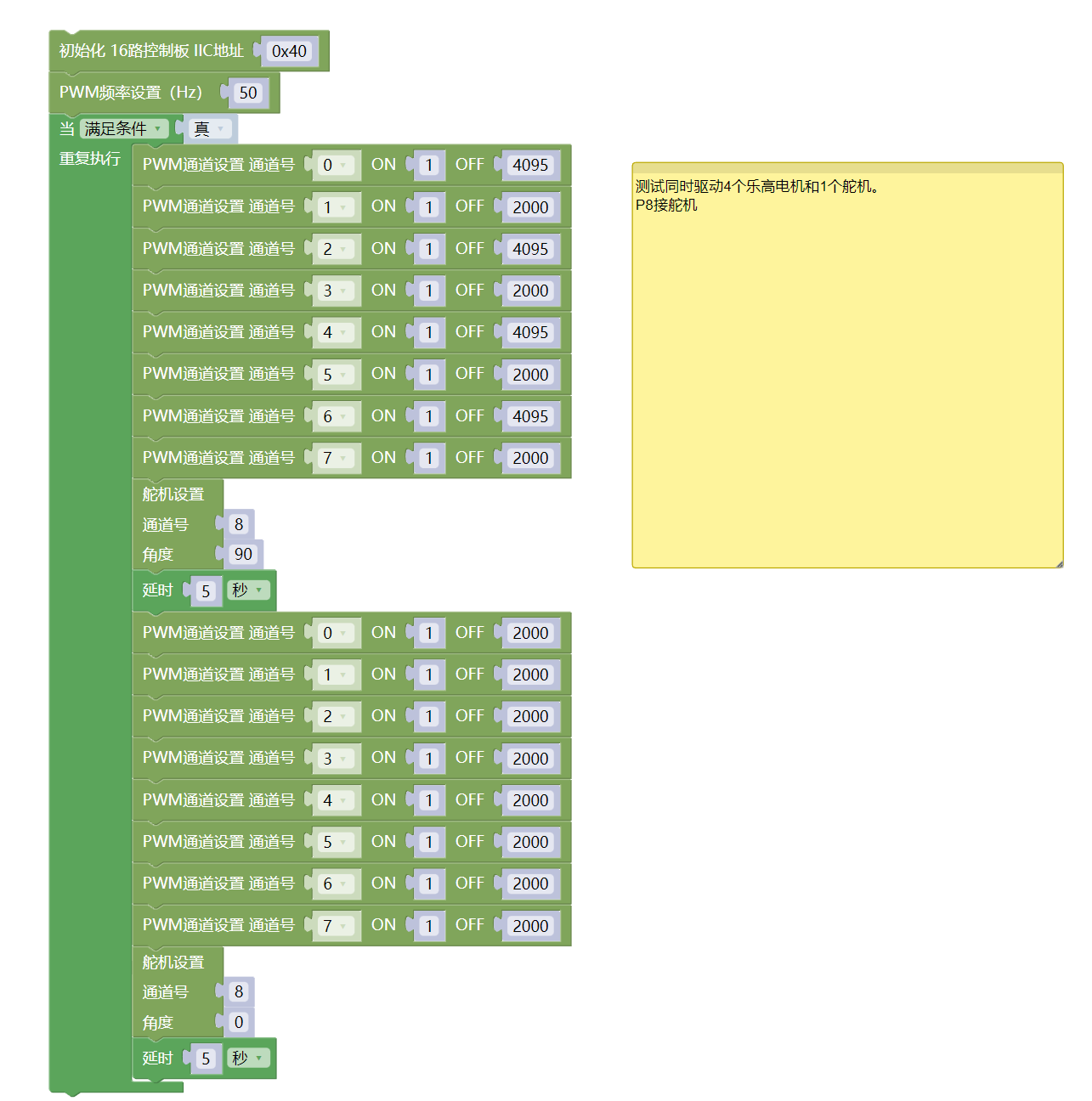
8, Mixly Example Program (Graphic Language)
Example Program (UNO Development Board):Click to download
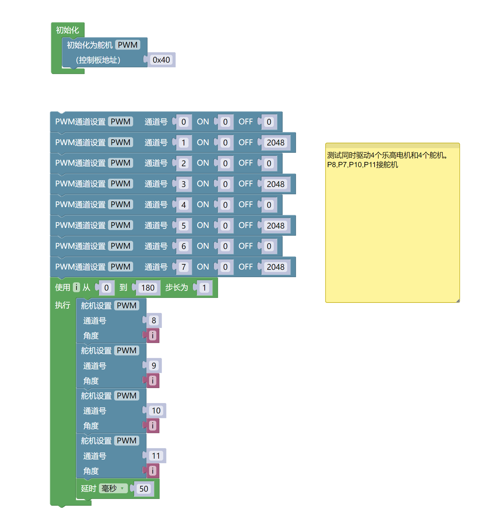
Example Program (ESP32 Development Board):Click to download
9. Setting up the Test Environment
Arduino UNO Test Environment Setup
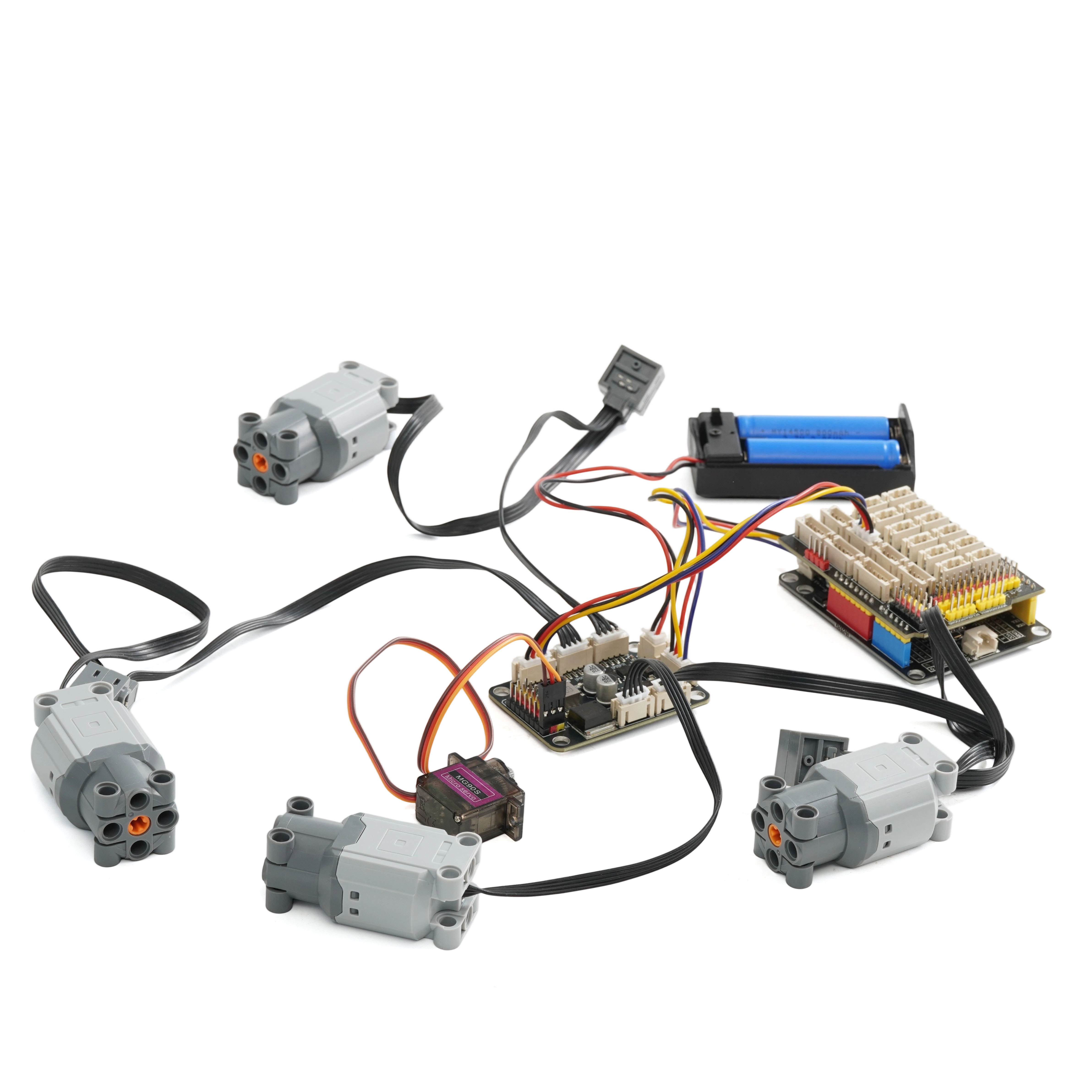
Prepare Components:
UNO-R3 Development Board *1
UNO-R3 Expansion Board *1
USB TYPE-C DATA CABLE *1
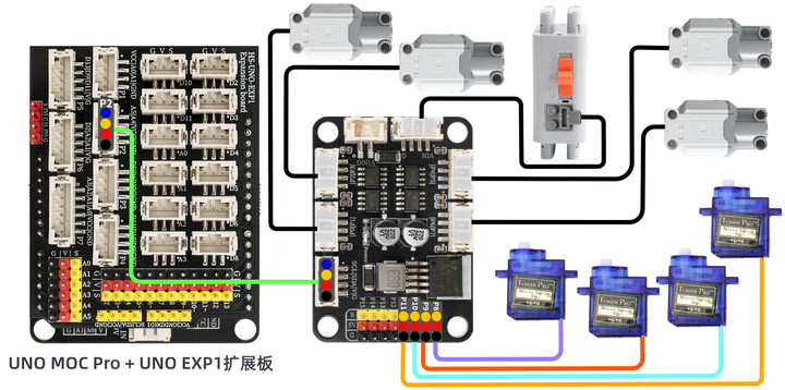
HS-F27 4-channel motor 8-channel servo expansion board*1
PH2.0 4P Double Head Terminal Line *1
6-9V battery box*1
LEGO motor*4
Servo*4
Circuit wiring diagram:
ESP32 Python test environment setup
10, video tutorial
Arduino UNO video tutorial: Click to view
ESP32 Python Video Tutorial:
11. Test Conclusion
Arduino UNO Test Conclusion:
Insert the code, connect the corresponding module, after powering on, the motor and servo will rotate simultaneously.