
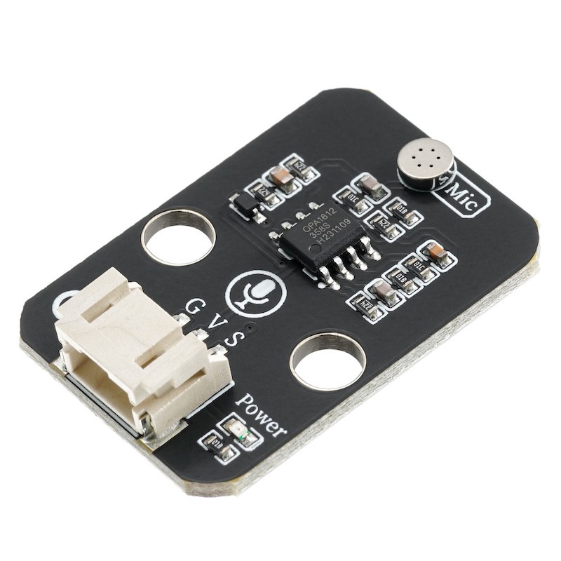
1. Introduction
The function of the sound sensor module is equivalent to a microphone (microphone).It is used to receive sound waves, display the vibration image of sound, but cannot measure the intensity of noise.The sensor is built-in with a sound-sensitive capacitive condenser microphone.Sound waves cause the piezoelectric film inside the microphone to vibrate, resulting in a change in capacitance, and thus producing a corresponding small voltage change.This voltage is then converted into a 0-5V voltage, which is accepted by the data acquisition device after A/D conversion and sent to the main control chip.
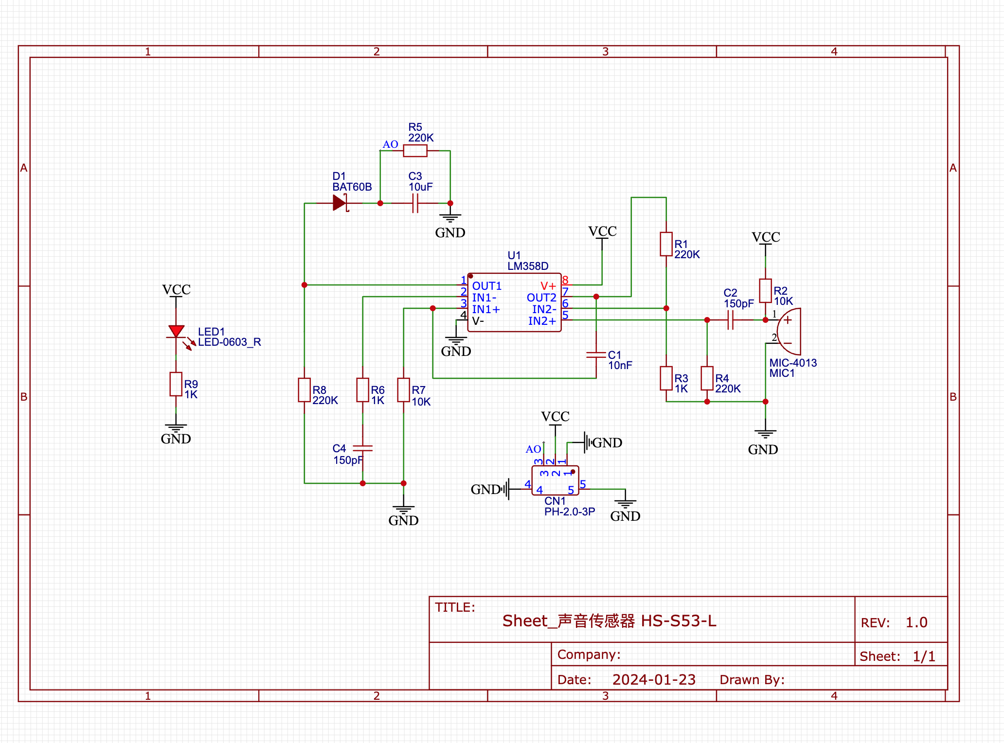
2. Schematic
Module Parameters
Pin Name | description |
|---|---|
G | GND (Negative Power Input) |
V | VCC (Positive Power Input) |
S | Analog Signal Pin |
Power Supply Voltage: 3.3V / 5V
Connection method: PH2.0 3P terminal
Installation method: Lego assembly
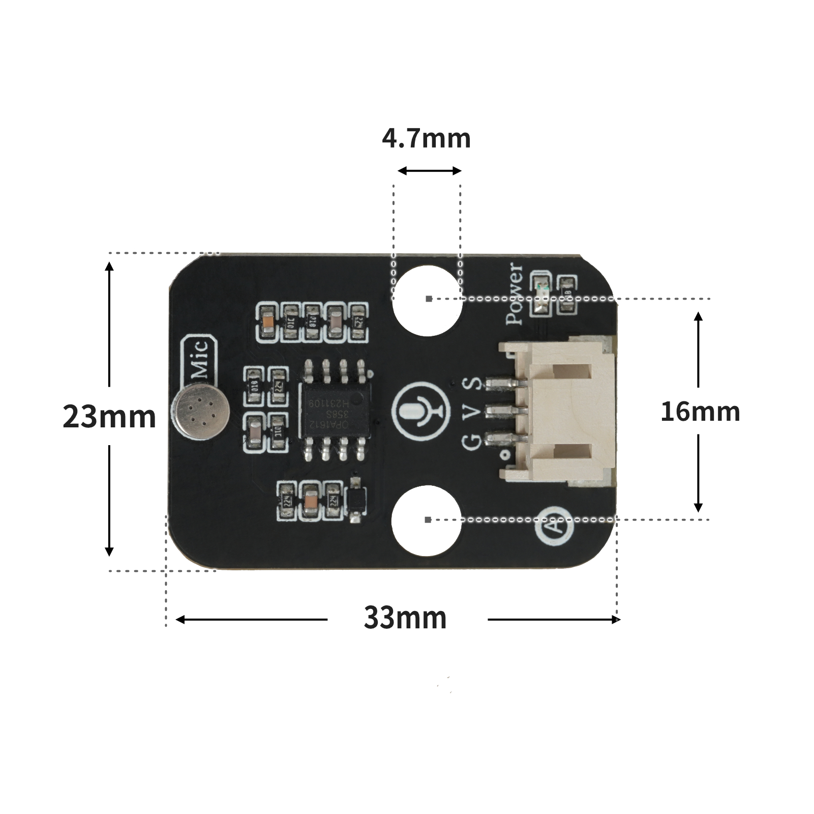
4, Circuit Board Size
5, Example Program Code
Example Program (UNO Development Board):Click to download
void setup(){
  Serial.begin(9600);
  pinMode(A0, INPUT);
  pinMode(6, OUTPUT);
}

void loop(){
  //高灵敏度声音传感器接A0;LED灯接D6
  if (analogRead(A0) > 500) {
    Serial.println(String("检测到声音:") + String(analogRead(A0)));
    digitalWrite(6,HIGH);
    delay(2000);

  } else {
    digitalWrite(6,LOW);
    Serial.println(String("未检测到声音 ") + String(analogRead(A0)));

  }

}
Example Program (ESP32 Development Board — Based on Python language, cannot be uploaded using Arduino IDE):
import machine
import time
adc32.atten(machine.ADC.ATTN_11DB)
pin4 = machine.Pin(4, machine.Pin.OUT)
while True:
if adc32.read_u16() >= 40000:
pin4.value(1)
time.sleep(1)
else:
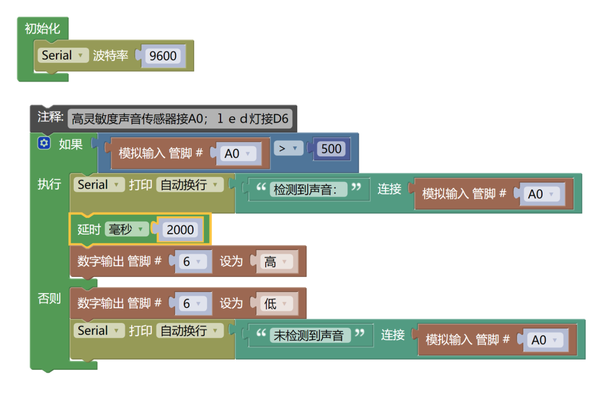
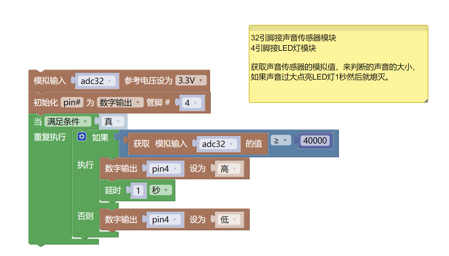
pin4.value(0)6, Miciqi Mixly Example Program (Graphical Language)
Example Program (UNO Development Board):Click to download
Example Program (ESP32 Development Board):Click to download
7, Test Environment Setup
Arduino UNO Test Environment Setup
Prepare Components:
HELLO STEM UNO R3 PRO DEVELOPMENT BOARD *1
HELLO STEM UNO R3 P EXPANSION BOARD *1
USB TYPE-C DATA CABLE *1
LED module (HS-F08L) *1
Sound Sensor Module (HS-S05L) *1
PH2.0 3P double-ended terminal line
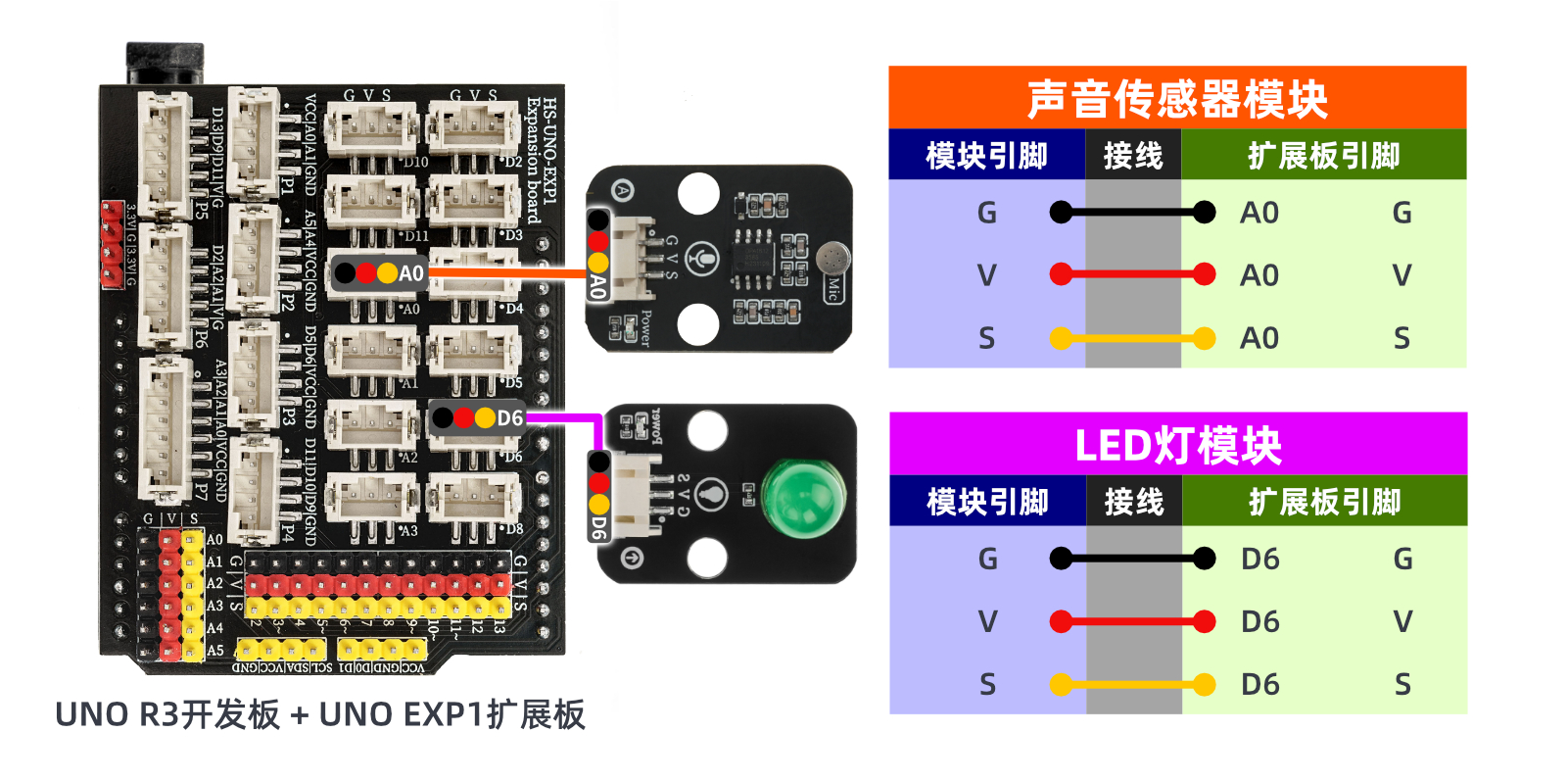
Circuit wiring diagram:
ESP32 Python test environment setup
Prepare Components:
Circuit wiring diagram:
8. Video tutorial
Video tutorial:Click to view
9. Test conclusion
Arduino UNO Test Conclusion:After the device is connected to the line, upload the above program to the Arduino uno development board, open the serial monitor, and if the analog value of the sound sensor is greater than the set threshold (detecting sound), the LED light will be on for 2 seconds, otherwise, the LED light will be off.