
1. Introduction
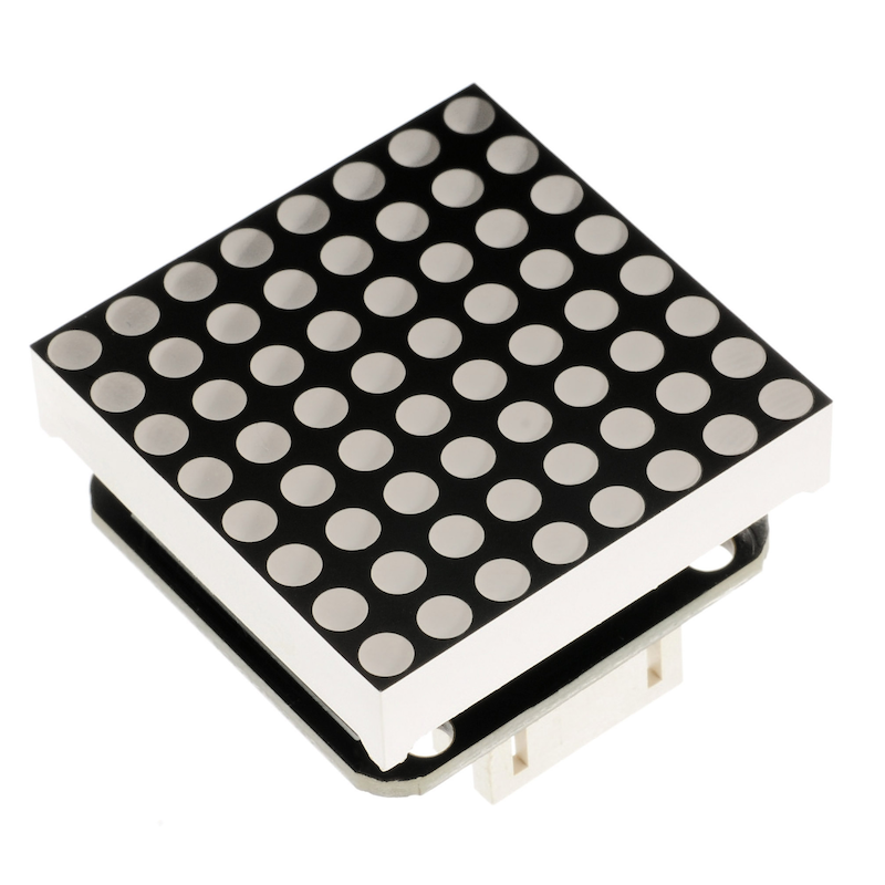
The 8*8 dot matrix module is driven by MAX7219, which is an integrated serial input/output display driver, only 3 IO ports are needed to drive 1 dot matrix, the dot matrix display has no flicker and supports cascading,The 8x8 dot matrix module is driven by Max7219, which uses three-wire serial communication. When receiving Arduino data, it stores the data in the internal 8x8 bit static RAM of the chip, and then controls the high and low levels of each pin of the 8x8 dot matrix module through Max7219 to achieve the display purpose.
2. Schematic
8X8-dot matrix display-HS-F13P schematicClick to view
Module Parameters
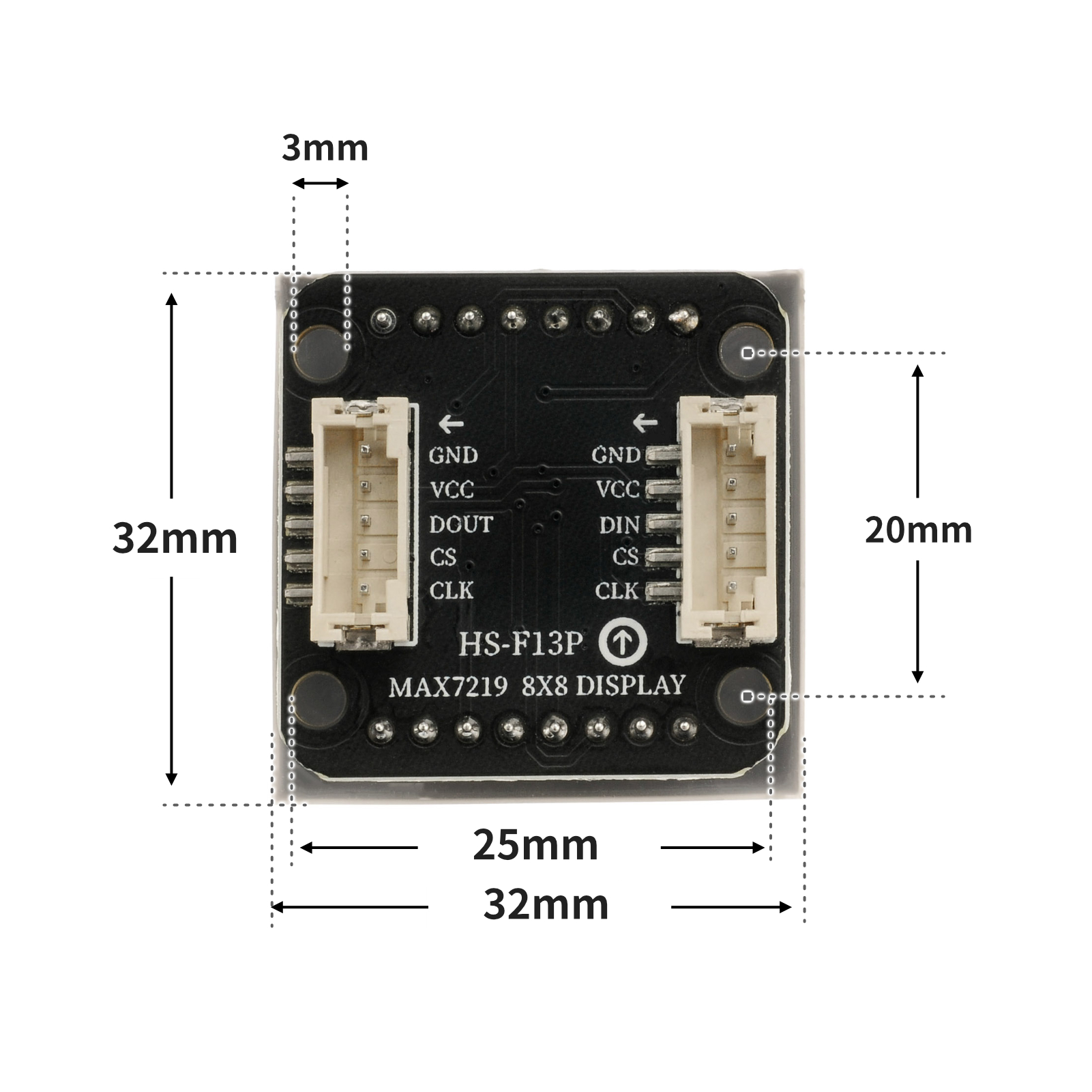
Pin Name | description |
|---|---|
CLK | clock pin |
CS | latch pin |
DIN | Data pin |
VCC | VCC (Positive Power Input) |
GND | GND (Negative Power Input) |
Power Supply Voltage: 3.3V / 5V
Connection method: PH2.0 socket
Installation method: Screw fixed
4, Circuit Board Size
5 of Arduino IDE example program
Attention: If prompted with an error message about the library file during program upload, please import the library file first!
Arduino IDE Library Download and Import Tutorial:Click to view
Example program (UNO development board):
#include <SPI.h>
#include <Adafruit_GFX.h>
#include <Max72xxPanel.h>
Max72xxPanel myMatrix = Max72xxPanel(9,1,1);
uint8_t LEDArray[8];
const uint8_t LedArray1[8] PROGMEM ={0x00,0x18,0x24,0x00,0x00,0xa5,0x42,0x00};
const uint8_t LedArray2[8] PROGMEM ={0x00,0x24,0x18,0x00,0x00,0x24,0xc3,0x00};
void setup(){
myMatrix.setRotation(0,3);
myMatrix.fillScreen(0);
myMatrix.write();
}
void loop(){
//MAX7219上显示笑脸和哭脸各1秒
memcpy_P(&LEDArray, &LedArray1, 8);
for(int index_i=0; index_i<8; index_i++)
{
for(int index_j=0*8; index_j<0*8+8; index_j++)
{
if((LEDArray[index_i]&0x01)>0)
myMatrix.drawPixel(index_j, 7-index_i,1);
else
myMatrix.drawPixel(index_j, 7-index_i,0);
LEDArray[index_i] = LEDArray[index_i]>>1;
}
}
myMatrix.write();
delay(1000);
memcpy_P(&LEDArray, &LedArray2, 8);
for(int index_i=0; index_i<8; index_i++)
{
for(int index_j=0*8; index_j<0*8+8; index_j++)
{
if((LEDArray[index_i]&0x01)>0)
myMatrix.drawPixel(index_j, 7-index_i,1);
else
myMatrix.drawPixel(index_j, 7-index_i,0);
LEDArray[index_i] = LEDArray[index_i]>>1;
}
}
myMatrix.write();
delay(1000);
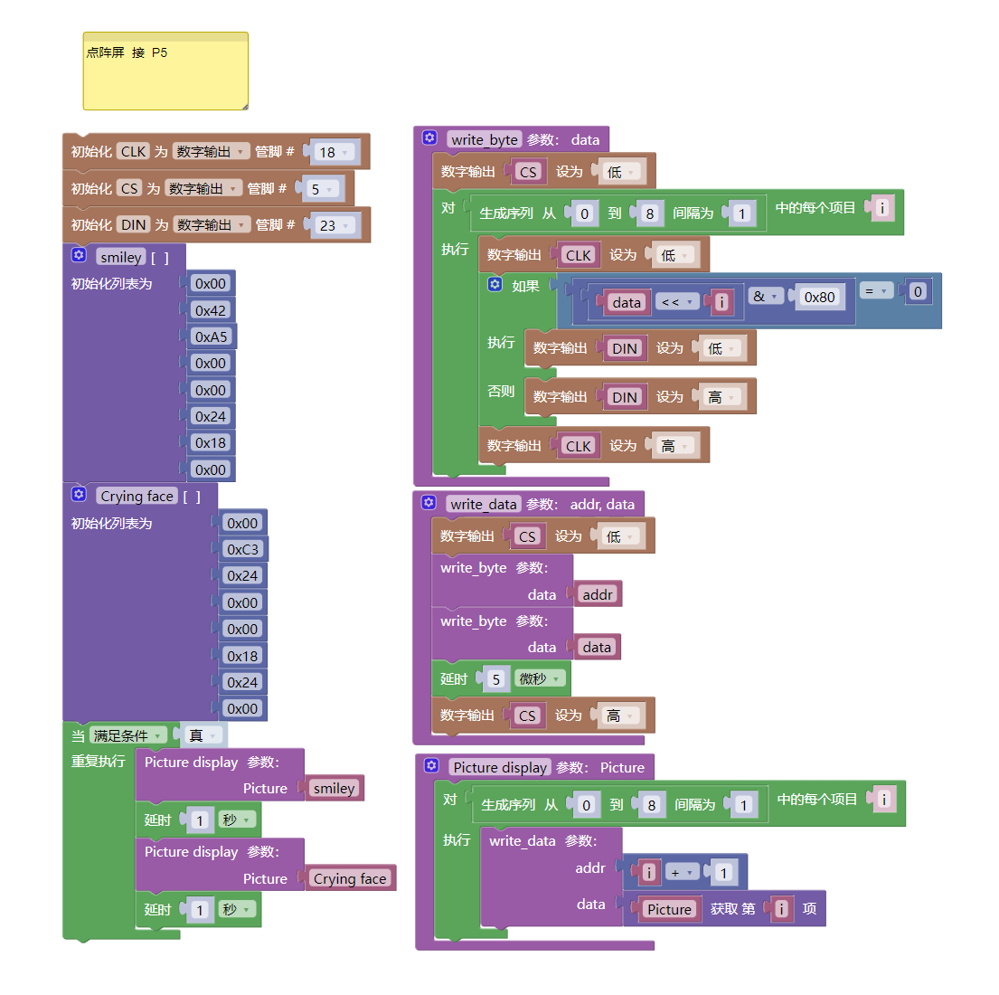
}6, ESP32 Python Example (for Mixly IDE/Misashi)
Choose the development board Python ESP32 [ESP32 Generic(4MB)] and upload in code mode
Attention: If prompted with an error message about the library file during program upload, please import the library file first!
Download and import tutorial for Mixly IDE ESP32 library:Click to view
Example program (ESP32-Python):
import machine
import time

def write_byte(data):
    CS.value(0)
    for i in range(0, 8, 1):
        CLK.value(0)
        if ((data<<i)&0x80) == 0:
            DIN.value(0)
        else:
            DIN.value(1)
        CLK.value(1)

def write_data(addr, data):
    CS.value(0)
    write_byte(addr)
    write_byte(data)
    time.sleep_us(5)
    CS.value(1)

def Picture_display(Picture):
    for i in range(0, 8, 1):
        write_data(i + 1, Picture[i])


CLK = machine.Pin(18, machine.Pin.OUT)
CS = machine.Pin(5, machine.Pin.OUT)
DIN = machine.Pin(23, machine.Pin.OUT)
smiley = [0x00, 0x42, 0xA5, 0x00, 0x00, 0x24, 0x18, 0x00]
Crying_face = [0x00, 0xC3, 0x24, 0x00, 0x00, 0x18, 0x24, 0x00]
while True:
    Picture_display(smiley)
    time.sleep(1)
    Picture_display(Crying_face)
    time.sleep(1)
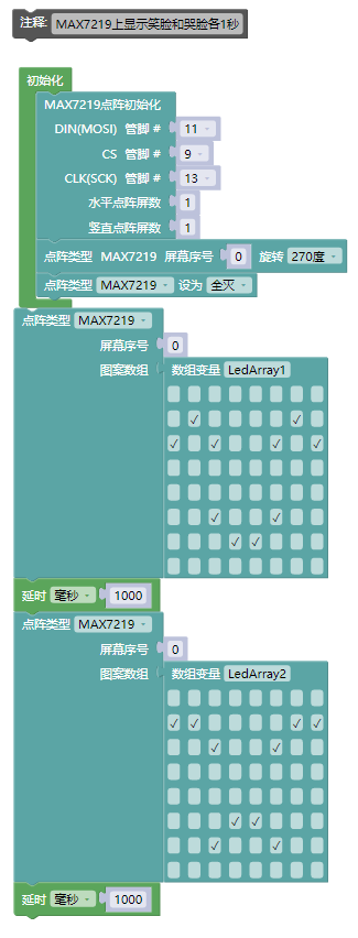
7, Mixly example program (graphical language)
Example program (UNO development board):Click to download
Attention: If prompted with an error message about the library file during program upload, please import the library file first!
Download and import tutorial of Mixly IDE Arduino library:Click to view
Example Program (ESP32 Development Board):Click to download
Attention: If prompted with an error message about the library file during program upload, please import the library file first!
Download and import tutorial for Mixly IDE ESP32 library:Click to view
8. Setting up the Test Environment
Arduino UNO Test Environment Setup
Prepare Components:
HELLO STEM UNO R3 PRO DEVELOPMENT BOARD *1
HELLO STEM UNO R3 P Expansion Board *1
USB TYPE-C DATA CABLE *1
8X8 dot matrix display (HS-F13P) *1
PH2.0 5P connector to Dupont wire *1
Circuit wiring diagram:
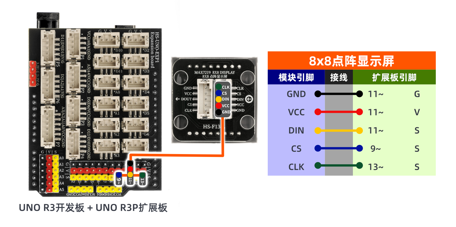
ESP32 Test Environment Setup
Prepare Components:
ESP32EA MOC development board *1
ESP32-EXP1 Expansion Board *1
USB TYPE-C DATA CABLE *1
8X8 dot matrix display (HS-F13P) *1
PH2.0 5P *1
Circuit wiring diagram:Pending update...

9, Video tutorial
Video tutorial:Click to view
10, Test results
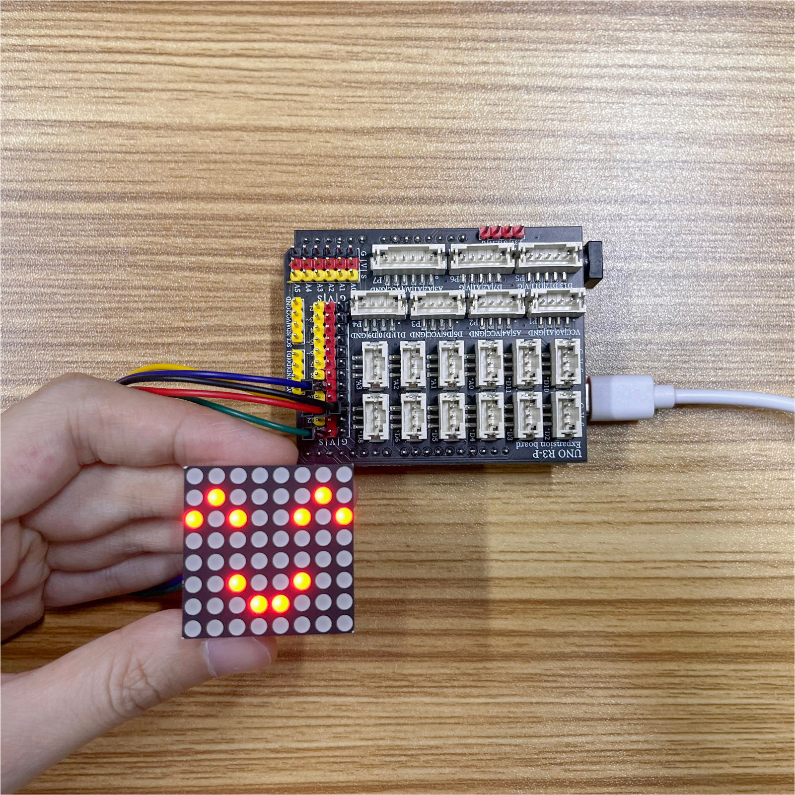
Arduino UNO test results:
After the device is connected to the wire, burn the above program to the development board, press the reset button, and you will see the matrix display smiling and crying faces in a loop.
ESP32 Test Results:
Pending update...