
1. Introduction
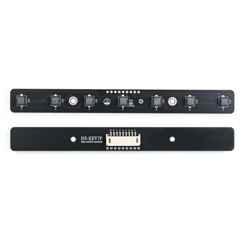
HS-KEY7P is a 7-way independent touch key input module designed specifically for embedded and STEAM education scenarios, providing a stable and reliable digital input interface, which can be directly connected to microcontrollers, development boards, and other systems to realize human-computer interaction functions.
An independent key is also known as a touch switch, which is operated by applying pressure in the direction of the switch operation to meet the operating force conditions, and the switch is closed to connect; when the pressure is released, the switch is opened; the internal structure relies on the change in force of the metal spring to achieve the connection and disconnection.
2. Schematic
HS-KEY7P 7P push button module Click to view
Module Parameters
Pin Name | description |
|---|---|
G | GND (Negative Power Input) |
V | VCC (Positive Power Input) |
1 | Digital Signal Pin |
2 | Digital Signal Pin |
3 | Digital Signal Pin |
4 | Digital Signal Pin |
5 | Digital Signal Pin |
6 | Digital Signal Pin |
7 | Digital Signal Pin |
Power Supply Voltage: 3.3V / 5V
Connection method: PH2.0 terminal wire
Installation method: Screw fixed
4, Circuit Board Size

5 of Arduino IDE example program
Attention: If prompted with an error message about the library file during program upload, please import the library file first!
Arduino IDE Library Download and Import Tutorial:Click to view
Example program (UNO development board):
#include <Adafruit_NeoPixel.h>

volatile int brightness;
Adafruit_NeoPixel rgb_display_A1 = Adafruit_NeoPixel(10,A1,NEO_GRB + NEO_KHZ800);
float tonelist[7]={1046.5,1174.7,1318.5,1396.9,1568,1760,1975.5};

void setup(){
  brightness = 80;
  rgb_display_A1.begin();
  rgb_display_A1.setBrightness(brightness);
  pinMode(2, INPUT);
  pinMode(3, INPUT);
  pinMode(4, INPUT);
  pinMode(5, INPUT);
  pinMode(6, INPUT);
  pinMode(7, INPUT);
  pinMode(8, INPUT);
}

void loop(){
  //do,re,mi,fa,so,la,si7个触碰开关分别接2,D3,D4,D5,D6,D7,D8;无源蜂鸣器接A5;按下不同的铵钮,播放对应的音调。

  if (digitalRead(2) == LOW) {
    //白灯亮。
    pinMode(A0, OUTPUT);
    tone(A0,tonelist[0]);
    delay(100);
    for (int i = 1; i <= 10; i = i + (1)) {
      rgb_display_A1.setPixelColor(i - 1, (((255 & 0xffffff) << 16) | ((255 & 0xffffff) << 8) | 255));
    }
    rgb_display_A1.show();

  } else if (digitalRead(3) == LOW) {
    pinMode(A0, OUTPUT);
    tone(A0,tonelist[1]);
    delay(100);
    //红灯亮。
    for (int i = 1; i <= 10; i = i + (1)) {
      rgb_display_A1.setPixelColor(i - 1, (((255 & 0xffffff) << 16) | ((0 & 0xffffff) << 8) | 0));
    }
    rgb_display_A1.show();
  } else if (digitalRead(4) == LOW) {
    pinMode(A0, OUTPUT);
    tone(A0,tonelist[2]);
    delay(100);
    //绿灯亮。
    for (int i = 1; i <= 10; i = i + (1)) {
      rgb_display_A1.setPixelColor(i - 1, (((0 & 0xffffff) << 16) | ((255 & 0xffffff) << 8) | 0));
    }
    rgb_display_A1.show();
  } else if (digitalRead(5) == LOW) {
    pinMode(A0, OUTPUT);
    tone(A0,tonelist[3]);
    delay(100);
    //深蓝灯亮。
    for (int i = 1; i <= 10; i = i + (1)) {
      rgb_display_A1.setPixelColor(i - 1, (((0 & 0xffffff) << 16) | ((0 & 0xffffff) << 8) | 255));
    }
    rgb_display_A1.show();
  } else if (digitalRead(6) == LOW) {
    pinMode(A0, OUTPUT);
    tone(A0,tonelist[4]);
    delay(100);
    //黄灯亮。
    for (int i = 1; i <= 10; i = i + (1)) {
      rgb_display_A1.setPixelColor(i - 1, (((255 & 0xffffff) << 16) | ((255 & 0xffffff) << 8) | 0));
    }
    rgb_display_A1.show();
  } else if (digitalRead(7) == LOW) {
    pinMode(A0, OUTPUT);
    tone(A0,tonelist[5]);
    delay(100);
    //紫色灯亮。
    for (int i = 1; i <= 10; i = i + (1)) {
      rgb_display_A1.setPixelColor(i - 1, (((128 & 0xffffff) << 16) | ((0 & 0xffffff) << 8) | 255));
    }
    rgb_display_A1.show();
  } else if (digitalRead(8) == LOW) {
    pinMode(A0, OUTPUT);
    tone(A0,tonelist[6]);
    delay(100);
    //按下遥控器数字8,土黄色灯亮。
    for (int i = 1; i <= 10; i = i + (1)) {
      rgb_display_A1.setPixelColor(i - 1, (((255 & 0xffffff) << 16) | ((128 & 0xffffff) << 8) | 0));
    }
    rgb_display_A1.show();
  } else {
    pinMode(A0, OUTPUT);
    noTone(A0);
    delay(100);
    //按下遥控器数字0,灯熄灭。
    for (int i = 1; i <= 10; i = i + (1)) {
      rgb_display_A1.setPixelColor(i - 1, (((0 & 0xffffff) << 16) | ((0 & 0xffffff) << 8) | 0));
    }
    rgb_display_A1.show();

  }

}
6, ESP32 Python Example (for Mixly IDE/Misashi)
Choose the development board Python ESP32 [ESP32 Generic(4MB)] and upload in code mode
Attention: If prompted with an error message about the library file during program upload, please import the library file first!
Download and import tutorial for Mixly IDE ESP32 library:Click to view
Example program (ESP32-Python):Pending update...
7, Mixly example program (graphical language)
Example program:Click to download
Attention: If prompted with an error message about the library file during program upload, please import the library file first!
Download and import tutorial of Mixly IDE Arduino library:Click to view

Example Program (ESP32 Development Board):Click to download
Attention: If prompted with an error message about the library file during program upload, please import the library file first!
Download and import tutorial for Mixly IDE ESP32 library:Click to view
Image pending update...
8. Setting up the Test Environment
Arduino UNO Test Environment Setup
Prepare Components:
HELLO STEM UNO R3 DEVELOPMENT BOARD *1
UNO-EXP4 Expansion Board*1
USB TYPE-C DATA CABLE *1
Passive buzzer module (HS-F08P) *1
7P key module (HS-KEY7P) *1
PH2.0 3P dual headed terminal line *1
PH2.0-7P connector to Dupont *1
Circuit wiring diagram:

ESP32 Test Environment Setup
Prepare Components:Pending update...
Circuit wiring diagram:Pending update...
9, Video tutorial
Video tutorial:Pending update...
10, Test results
Arduino UNO test results:
After the device is connected to the wire, burn the above program to the Arduino UNO development board, and connect the power.Trigger the signal port output high and low levels, and achieve the purpose by judging the state of the signal port level.Pressing the button 1-7 will cause the buzzer to sound the corresponding melody.
ESP32 Test Results:
Pending update...