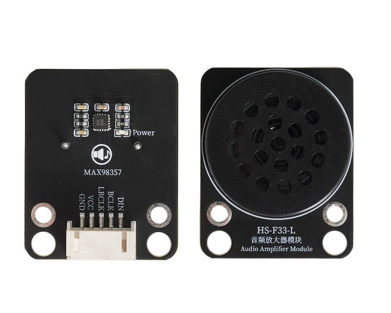
1. Introduction
An audio amplifier module is an electronic module used to enhance the power of audio signals, which can amplify weak audio electrical signals (such as signals output from microphones, players), and boost the voltage and current strength of the signal, making the sound louder and clearer.The amplified audio signal is output from the module, connected to speaker and other load devices, driving the load to emit sound.Note: The UNO development board does not have enough performance to drive this module.
2. Schematic
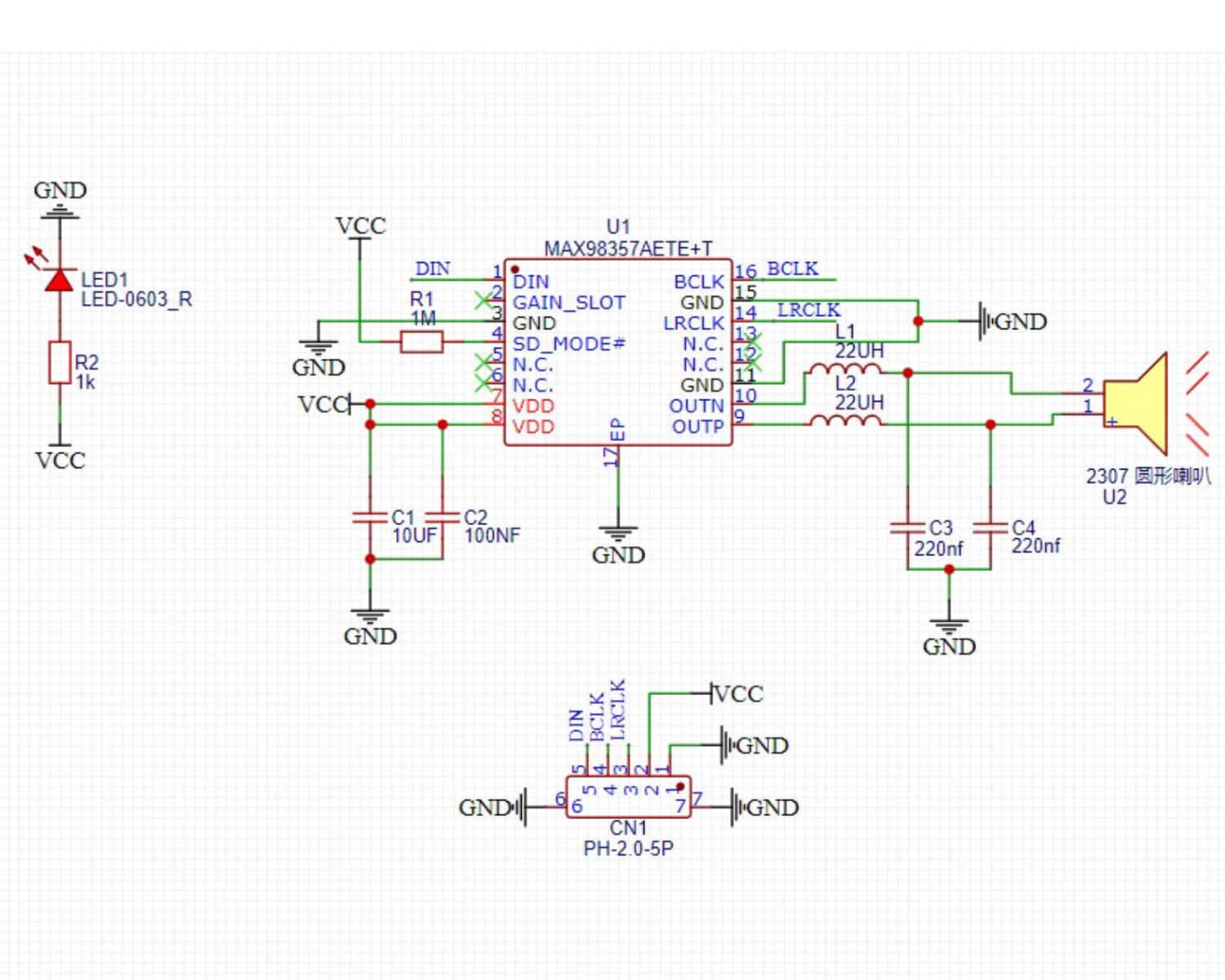
Module Parameters
Pin Name | description |
|---|---|
G | GND (Negative Power Input) |
V | VCC (Positive Power Input) |
LRCLK | Left and Right Clock Pins |
BCLK | Bit Clock Pin |
DIN | Data Input Pin |
Power supply voltage: 3.3-5V
Connection method: PH2.0 4P terminal wire
Installation method: Modular fixed
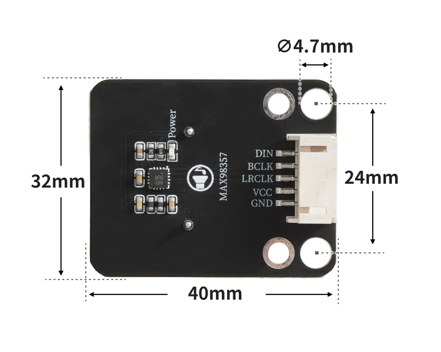
4, Circuit Board Size
Add Arduino Library File
Reference here if you don't know how to use library files:Install and use library files
Library file download: Click to download
Unzip the downloaded Arduino library files to the desktop and then place them in Arduino's libraries folder.
6, Add MicroPython environment library file
Please click here for reference if you cannot install library files
7. Arduino IDE example program
Example program (ESP32 development board): Click to download
#define SAMPLE_RATE (44100)
#define I2S_MIC_WS (12)
#define I2S_MIC_SD (14)
#define I2S_MIC_BCK (13)
#define I2S_PORT_0 (I2S_NUM_0)
#define bufferLen (1024)
#define SAMPLE_RATE (44100)
#define bufferLen (1024)
#define I2S_SPK_DIN (25)
#define I2S_SPK_BCLK (27)
#define I2S_SPK_LRCLK (26)
#define I2S_PORT_1 (I2S_NUM_1)
#include "Arduino.h"
#include "driver/i2s.h"
#include "Arduino.h"
#include "driver/i2s.h"

int16_t sBuffer_RX[bufferLen];
size_t bytesIn = 0;
int16_t sBuffer_TX[bufferLen*2];
size_t bytesOut = 0;

void I2s_Mic_Init()
 {
   i2s_config_t i2s_config_RX{};
   i2s_config_RX.mode = (i2s_mode_t)(I2S_MODE_MASTER | I2S_MODE_RX);
   i2s_config_RX.sample_rate = SAMPLE_RATE;
   i2s_config_RX.bits_per_sample = I2S_BITS_PER_SAMPLE_16BIT;
   i2s_config_RX.channel_format = I2S_CHANNEL_FMT_ONLY_LEFT;
   i2s_config_RX.communication_format = (i2s_comm_format_t)(I2S_COMM_FORMAT_I2S | I2S_COMM_FORMAT_I2S_MSB);
   i2s_config_RX.intr_alloc_flags = ESP_INTR_FLAG_LEVEL1;
   i2s_config_RX.dma_buf_count = 8;
   i2s_config_RX.dma_buf_len = bufferLen;
   i2s_config_RX.use_apll = false;
   i2s_driver_install(I2S_PORT_0, &i2s_config_RX, 0, NULL);
   i2s_pin_config_t pin_config_RX{};
   pin_config_RX.mck_io_num = I2S_PIN_NO_CHANGE;
   pin_config_RX.bck_io_num = I2S_MIC_BCK;
   pin_config_RX.ws_io_num = I2S_MIC_WS;
   pin_config_RX.data_out_num = I2S_PIN_NO_CHANGE;
   pin_config_RX.data_in_num = I2S_MIC_SD;
   i2s_set_pin(I2S_PORT_0, &pin_config_RX);
   i2s_start(I2S_PORT_0);
 }
int16_t* Mic_Value()
 {
   i2s_read(I2S_PORT_0, sBuffer_RX, sizeof(sBuffer_RX), &bytesIn, portMAX_DELAY);
   for (int i = 0; i < bufferLen; i++)
   {
     sBuffer_RX[i] = sBuffer_RX[i]*2;
     if (sBuffer_RX[i] > (32767))
       sBuffer_RX[i] = (32767);
     else if (sBuffer_RX[i] < (-32768))
       sBuffer_RX[i] = (-32768);
   }
   return sBuffer_RX;
 }
void I2s_Spk_Init()
 {
   i2s_config_t i2s_config_TX{};
   i2s_config_TX.mode = (i2s_mode_t)(I2S_MODE_MASTER | I2S_MODE_TX);
   i2s_config_TX.sample_rate = SAMPLE_RATE;
   i2s_config_TX.bits_per_sample = I2S_BITS_PER_SAMPLE_16BIT;
   i2s_config_TX.channel_format = I2S_CHANNEL_FMT_RIGHT_LEFT;
   i2s_config_TX.communication_format = (i2s_comm_format_t)(I2S_COMM_FORMAT_I2S | I2S_COMM_FORMAT_I2S_MSB);
   i2s_config_TX.intr_alloc_flags = ESP_INTR_FLAG_LEVEL1;
   i2s_config_TX.dma_buf_count = 8;
   i2s_config_TX.dma_buf_len = bufferLen;
   i2s_config_TX.use_apll = false;
   i2s_driver_install(I2S_PORT_1, &i2s_config_TX, 0, NULL);
   i2s_pin_config_t pin_config_TX{};
   pin_config_TX.mck_io_num = I2S_PIN_NO_CHANGE;
   pin_config_TX.bck_io_num = I2S_SPK_BCLK;
   pin_config_TX.ws_io_num = I2S_SPK_LRCLK;
   pin_config_TX.data_out_num = I2S_SPK_DIN;
   pin_config_TX.data_in_num = I2S_PIN_NO_CHANGE;
   i2s_set_pin(I2S_PORT_1, &pin_config_TX);
   i2s_start(I2S_PORT_1);
 }
void Spk_Value(int16_t* sBuffer_RX)
 {
   for (int i = 0; i < bufferLen; i++)
   {
     sBuffer_TX[i*2] = sBuffer_RX[i];
     sBuffer_TX[i*2+1] = sBuffer_RX[i];
   }
   i2s_write(I2S_PORT_1, sBuffer_TX, sizeof(sBuffer_TX), &bytesOut, portMAX_DELAY);
 }

void setup(){
  I2s_Mic_Init();
  I2s_Spk_Init();
}

void loop(){
  Spk_Value(Mic_Value());
}
Example program (ESP32-S3 development board): Click to download
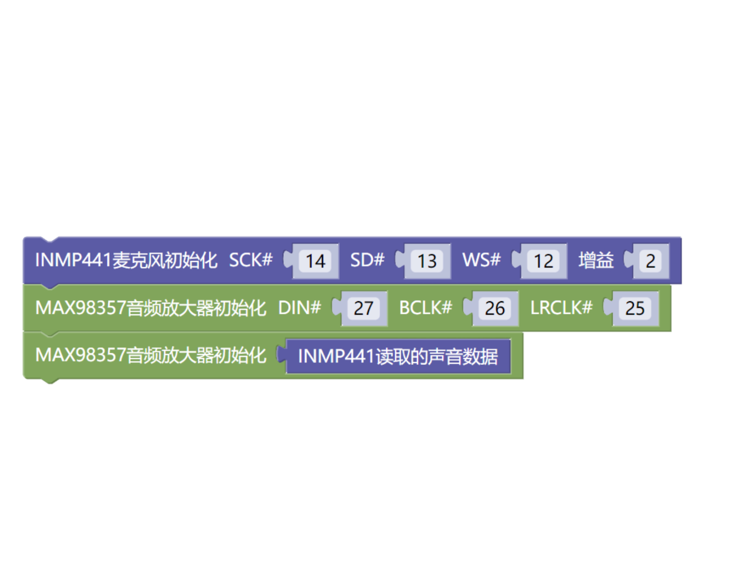
8, Mixly Example Program (Graphic Language)
Mixly Library (ESP32 Development Board - C Language Version):Click to download
Sample Program (ESP32 Development Board - C Language Version):Click to download
MiXin Mixly library file (ESP32-S3 development board - C language version): Click to download
Example Program (ESP32-S3 Development Board - C Language Version): Click to Download
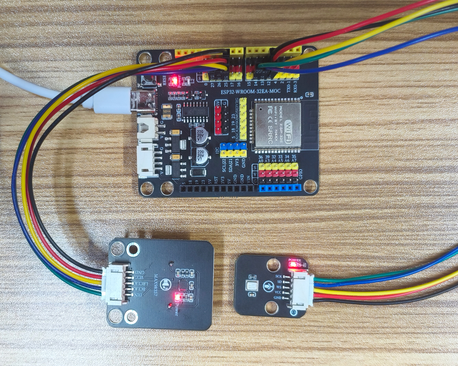
9. Setting up the Test Environment
Arduino ESP32 Test Environment Setup
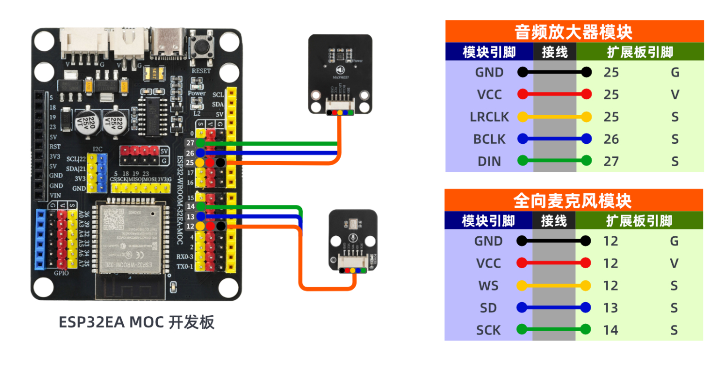
Prepare Components:
ESP32 Development Board *1
ESP32 EXP1 Expansion Board *1
USB TYPE-C DATA CABLE *1
HS-S05C-L Omnidirectional Microphone Module*1
HS-F33-L Audio Amplifier Module*1
PH2.0 5P PH2.0 terminal to Dupont wire *2
Circuit wiring diagram:
ESP32 Python test environment setup
10, video tutorial
Arduino UNO video tutorial: Click to view
ESP32 Python Video Tutorial:
11. Test Conclusion
Arduino UNO Test Conclusion:
Discover the all-directional microphone module that can realize the complete audio path of 'sound collection - audio amplification - sound playback'