
1. Introduction
2, Characteristics
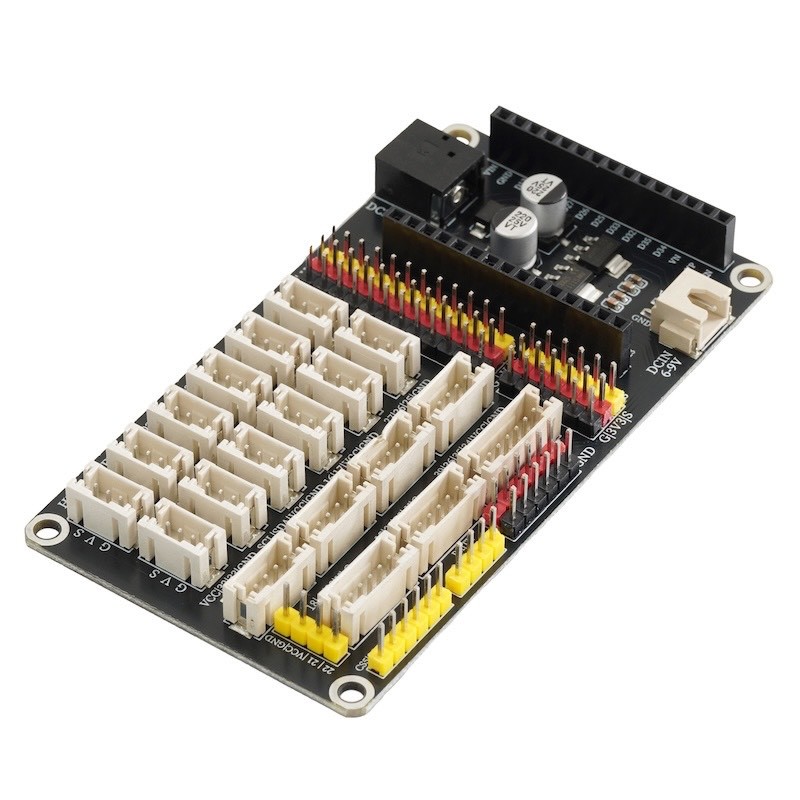
1, there is an IO port pin. (It can meet the need for connecting and plugging in expansion modules using DuPont wires)
2, There is an IO port with a PH2.0 3P socket, as well as 4 PH2.0 4P sockets, 2 PH2.0 5P sockets, and 1 PH2.0 6P socket.
3, featuring SPI communication interface pins, serial communication interface pins, I2C communication interface pins.
3, Expansion Board Parsing
Digital IO port PH2.0 3P socket (8-18,21) and digital IO port pin headers (all pin headers)
You can specify these IO ports as digital outputs, which means they can output high or low levels.
Simulated IO port PH2.0 3P socket (8,9,10,11,12,13,14,15,16,17,18) and simulated IO port pin header (1-16)
Can specify these IO ports for simulation input.
P1 socket
The sub-circuit is designed as VCC/32/33/GND for easy connection with some modules using a PH2.0 4P interface. (Compatible module: HS-SR04L)Ultrasonic Sensor)
P2 Socket
The socket circuit is designed as 22/21/VCC/GND for convenient connection with some modules using the PH2.0 4P interface. (Compatibility module: HS-S63-LTCS342 color sensor, HS-F14LTM1650 four-digit LED digital tube module, HS-F15LTM637 four-digit clock digital tube module, HS-F19LOLED display, HS-F21LLCD1602 display, )
P3 bracket
The socket circuit is designed as 16/17/VCC/GND for convenient connection with some modules using a PH2.0 4P interface.Voice recognition control module& HS-F04LMotor drive module& HS-F20LMotor Module, HS-F10LMotor drive module, HS-S49PLMP3 Audio Broadcast Module, HS-F23-L1-digit digital tube, HS-S60-LBluetooth module)
P4 socket
The socket circuit is designed as 27/26/25/GND for easy connection with some modules using a PH2.0 4P interface. (Adaptable module: HS-F05LTraffic Signal Module, HS-F01LRGB LED Module)
P5 Socket
This socket circuit is designed for 18/5/23/V/G and is convenient for mating with some modules using PH2.0 5P interfaces. (For example, HS-F13L)8x8 dot matrix display moduleHS-F24-L1-digit digital tube)
P6 seat
This sub-circuit is designed as 15/34/35/V/G for easy connection with some modules using a PH2.0 5P interface. (Adapted module: HS-S34L)Dual-axis joystick moduleHS-S32LRotary encoder)
P7 socket
The sub-circuit design is 39/36/35/34/V/G for easy connection with some modules using the PH2.0 6P interface.4P button module)