
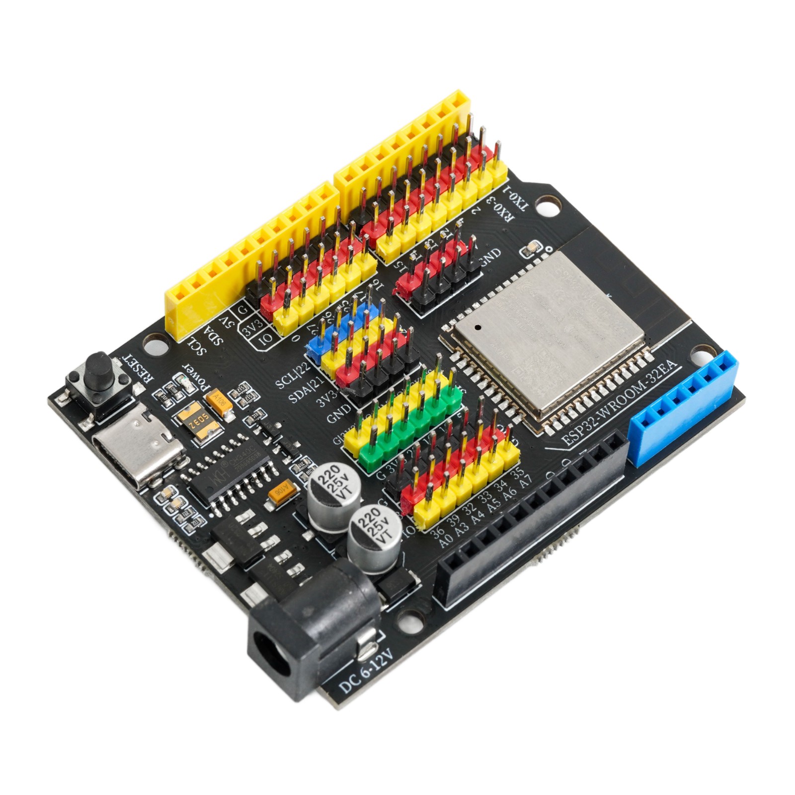
1. Introduction
ESP32-WROOM-32-N4.
LEIXIN official data manual:esp32-wroom-32e_esp32-wroom-32ue_datasheet_cn.pdf
2, Technical Specifications
Microcontroller | ESP32-WROOM-32E |
Operating Voltage | 3.3V |
Input Voltage (Recommended) | 6-9V (DC Direct Current) |
Digital Pin | 20 units |
Analog Input Pin | 6 units (32,33,34,35,36,39) |
Download Interface | USB Type-C |
Wireless Transmission Protocol | WiFi 802.11 b/g/n |
Bluetooth Standard | 4.2BR/EDR/BLE Standard |
Chip Clock Frequency | 240MHz |
External Flash | 4MB |
SRAM | 520KB |
Built-in ROM | 448KB |
3, Features
1. The original brand new ESP32-WROOM-32E module released by Espressif Systems in 2023 is used
2, Enhance power supply, G|V can provide a maximum output capability of 3.3V 40mA
3, Onboard circuit protection and power selection circuit
4, Type-C communication interface, no need to distinguish between positive and negative, more convenient
5, Support DC5525 input interface, allows 6-12VDC input
6, on-board 2.54mm pitch G|V|S expansion pin interface, without expansion board usage
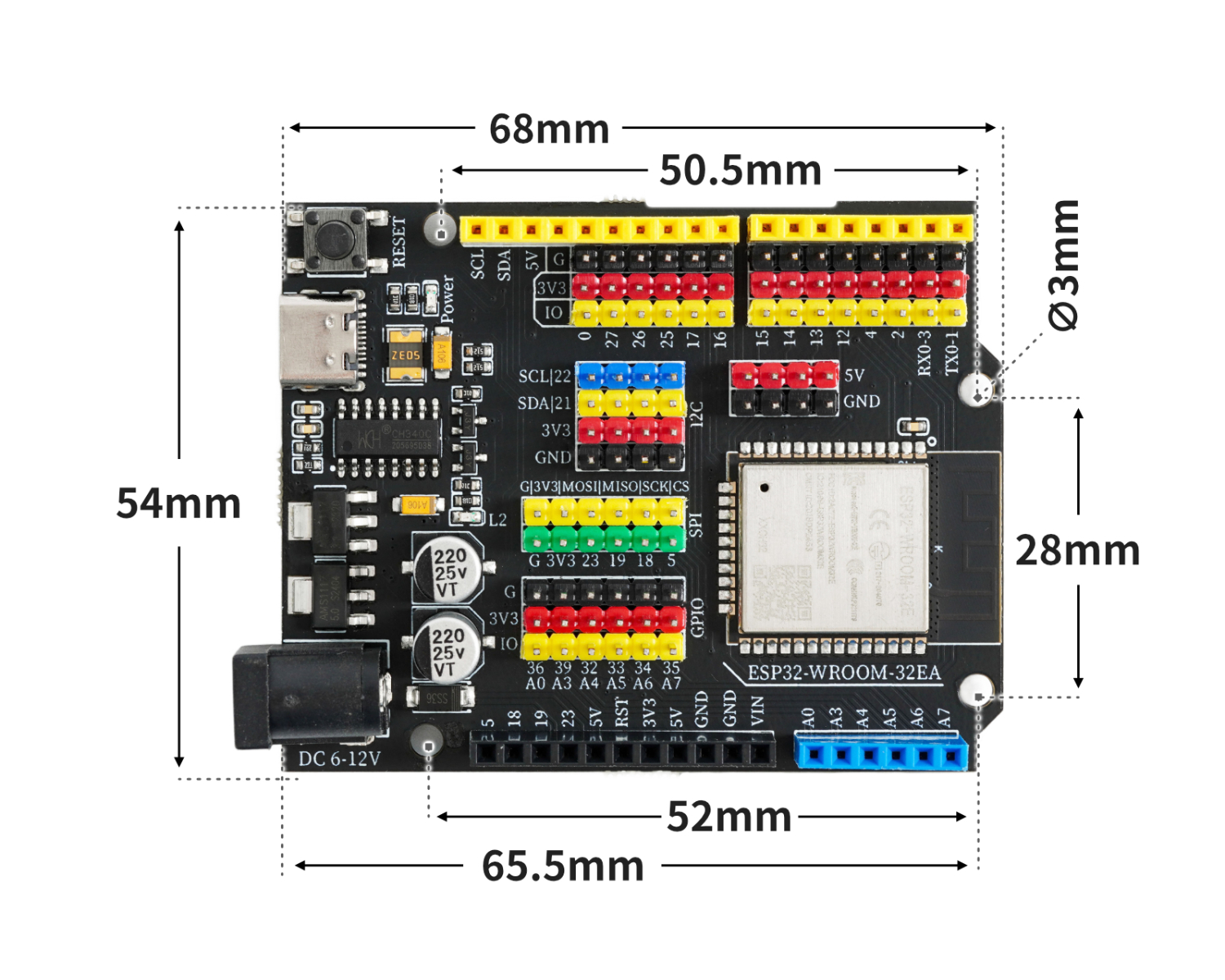
4, Circuit Board Size
5, Development board decoding
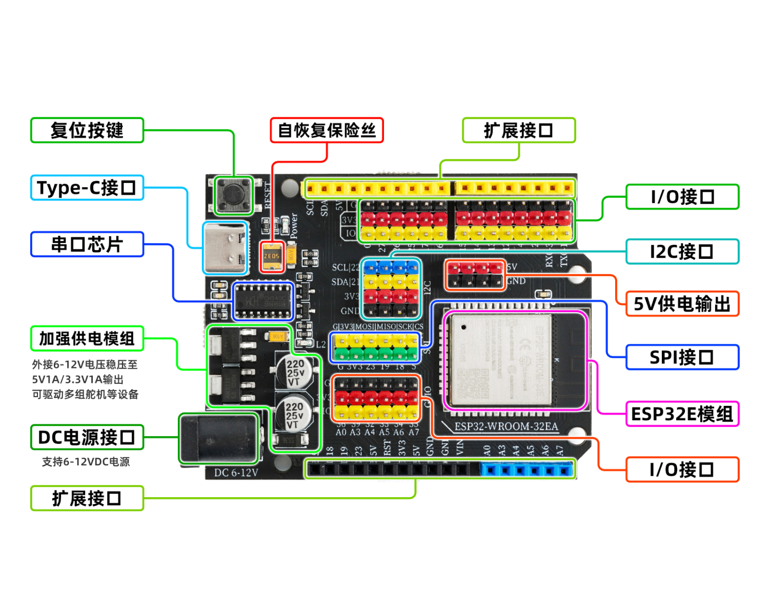
Reset button
Press the reset button and run the program again.Serial port chip
This chip is responsible for converting the data received from USB into serial data for the main control chip.5V/2A power module
The power module is responsible for the power supply service of the motherboard, the 6-12V power supply from the external access is stepped down to 5V/2A/10W output, and can drive multiple servos, toy motors, miniature slides and other devices.Self-recovery fuse
When the development board is connected incorrectly, causing a short circuit, the fuse will automatically disconnect the circuit connection between the development board and the computer, thereby protecting the computer USB port from being burnt or the computer from crashing.Type-C interface
responsible for data download and USB power supply.Automatic switching controller between external power supply and USB power supply
FDN340P field effect transistor + LMV358IDGKR amplifier composed of external power supply and USB power supply automatic switching control system.The development board is powered by USB interface by default. When an external power source is connected, the controller will automatically disconnect the USB power and switch to external power supply. After the external power source is disconnected, it will automatically switch back to USB power supply. This feature can protect the computer from the power interference of the development board's external power supply.ESP32E module
The ESP32-WROOM-32E main control chip is the brain of the development board, responsible for program storage, execution, computational processing, signal input and output, and other functions.
Expansion board interface
Used to interface with our company's配套 expansion board, convenient for plugging in modules.
6, Driver download and installation
Download and installation method for USB drivers for Windows 7, 8, 10, 11 systems:Click to view
Download of USB drivers for Mac OS system:Download and install instructions for CH34X USB serial Mac OS driver
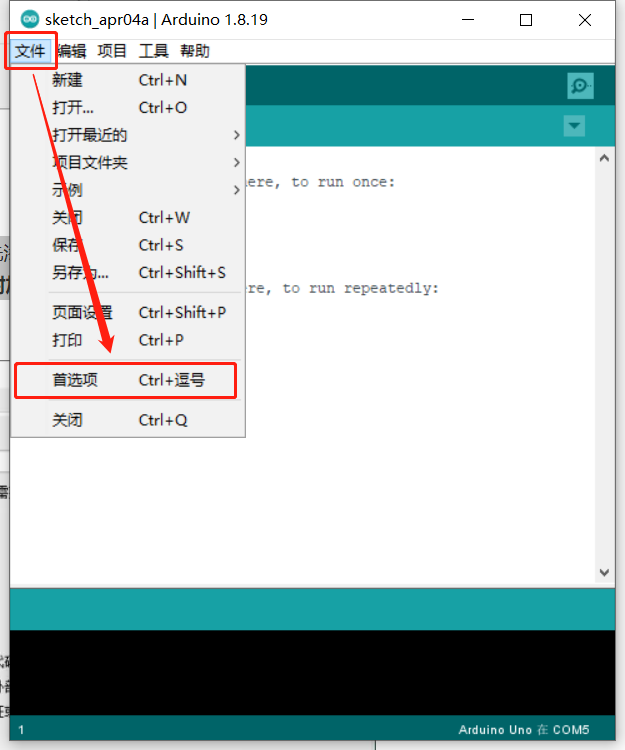
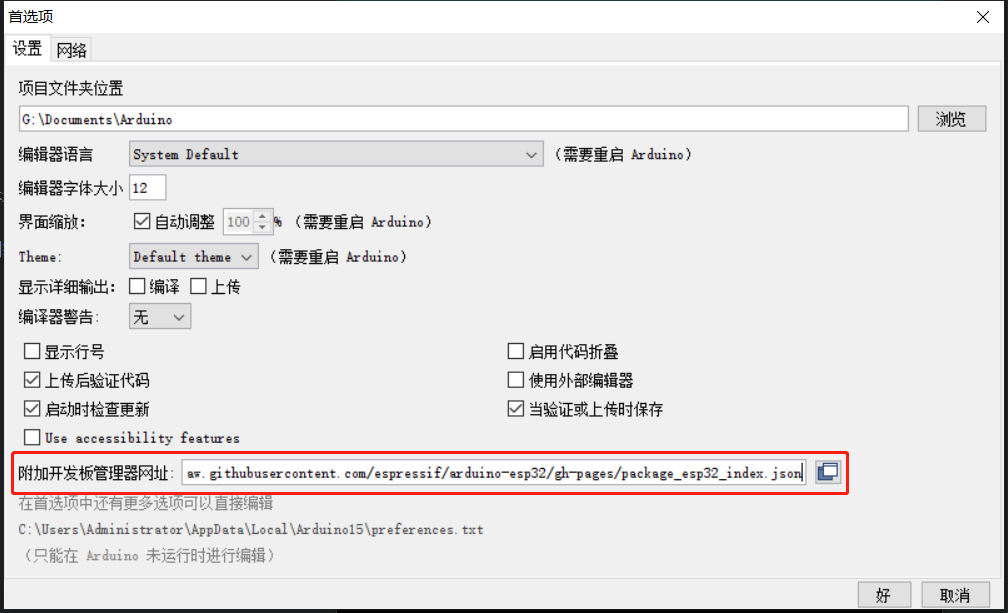
In order to develop ESP32 with Arduino IDE, you need to add an additional source to the Arduino IDE board manager and then install ESP32.We need to add the ESP32 development board additional URL first.Open the Preferences under the File menu.
Copy and paste the following link into the Additional Development Board Management website:
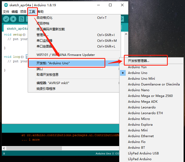
Install the ESP32 development board, select the Tools menu -> Board Manager...
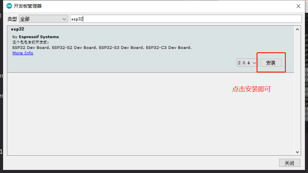
Search for esp32 in the search bar, you can see the esp32 library, select version 2.0.4, click install, and wait for the installation to complete.
Choose the corresponding development board ESP32 Dev Module,
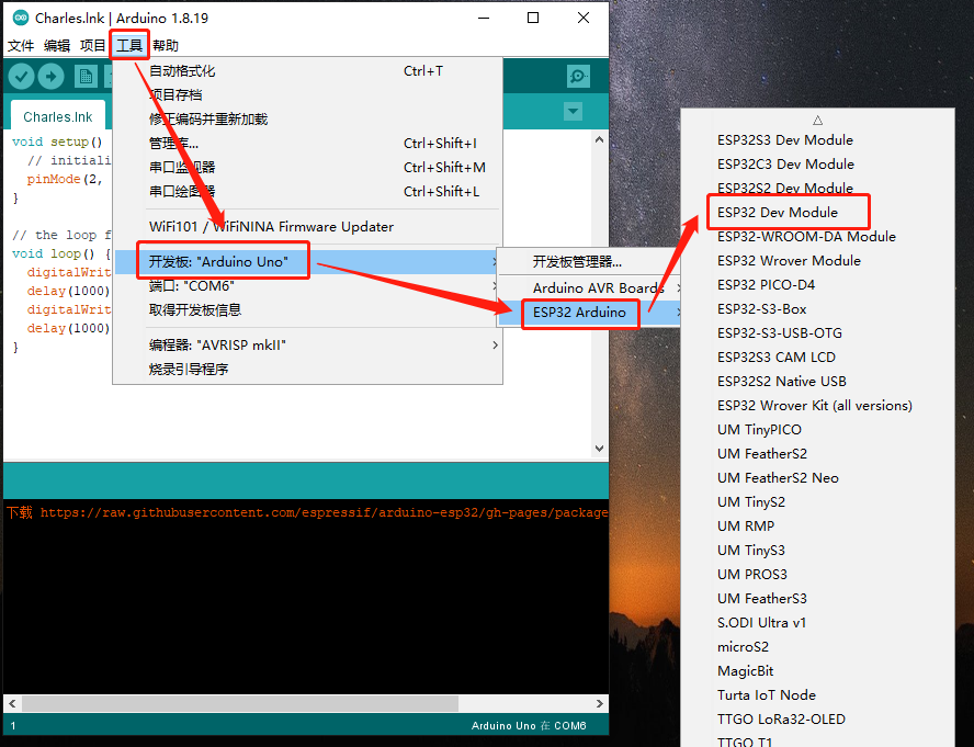
After selecting the development board, some options will appear in the tool menu. If you don't know how to debug, just use the default settings.
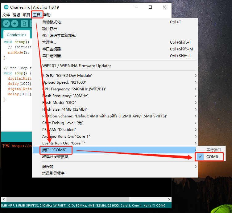
Next, select the port corresponding to the ESP32.
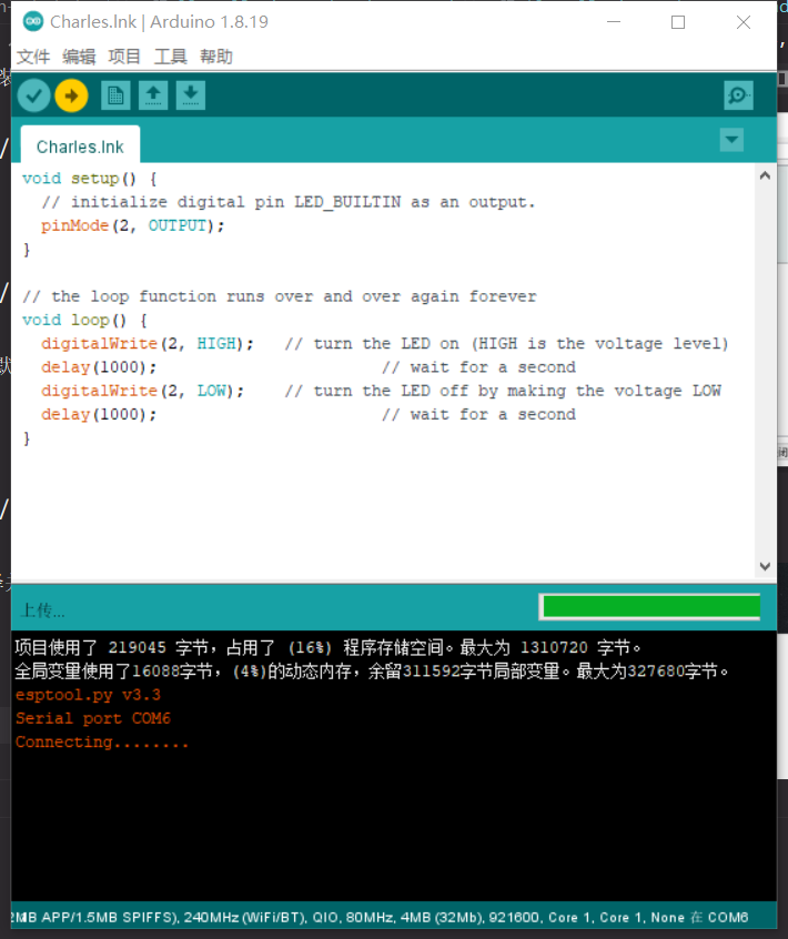
Finally, we open the test code within the sample program, compile, and run it.
Example program:Click to download
Pay attention!!! If the above methods do not work, you can refer to the following methods:Refer to the video.
Frequent questions: Upload failure solution: Remove the external modules from the 2nd, 5th, and 12th pins of the development board