
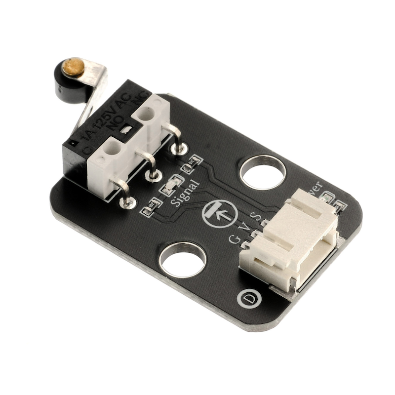
1. Introduction
2. Schematic
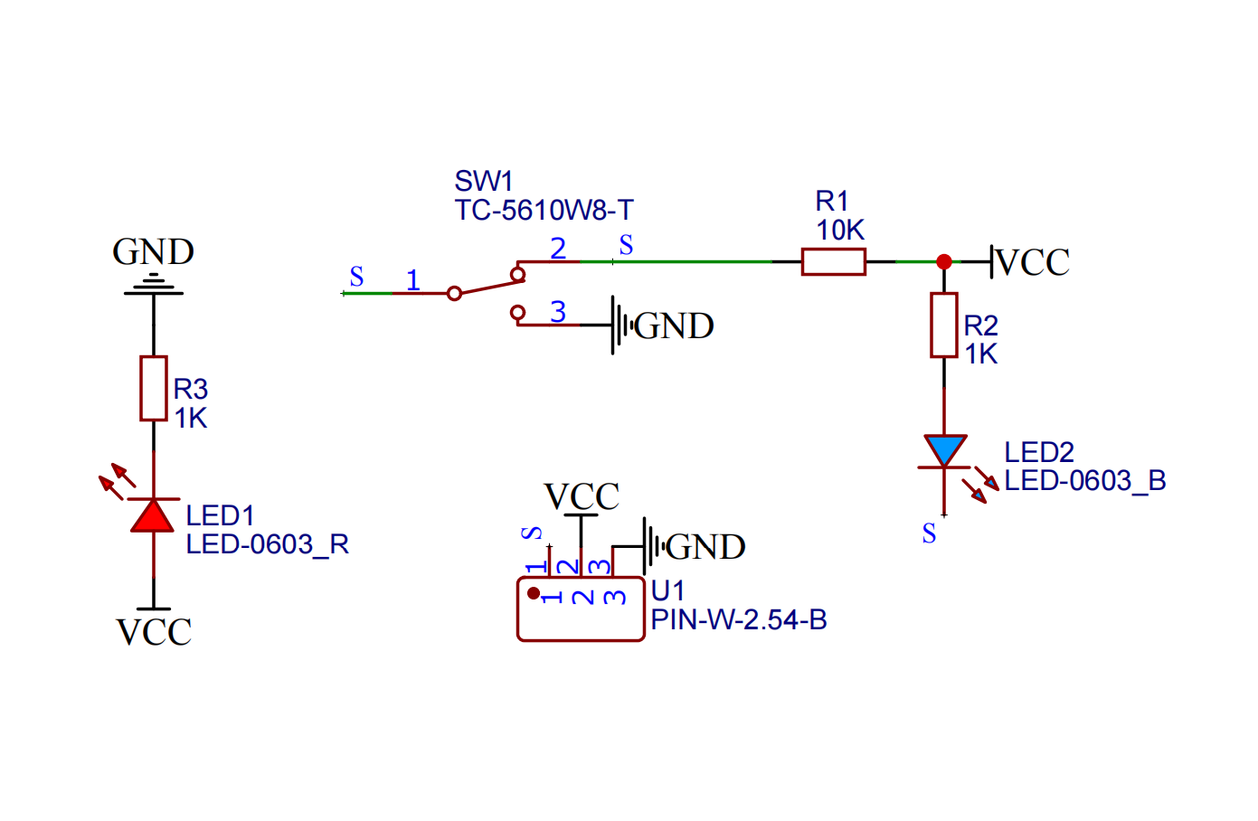
Module Parameters
Pin Name | description |
|---|---|
G | GND (Negative Power Input) |
V | VCC (Positive Power Input) |
S | Digital Signal Pin |
Power Supply Voltage: 3.3V / 5V
Connection method: PH2.0 3P terminal
Installation Method: Double Screw Fixed
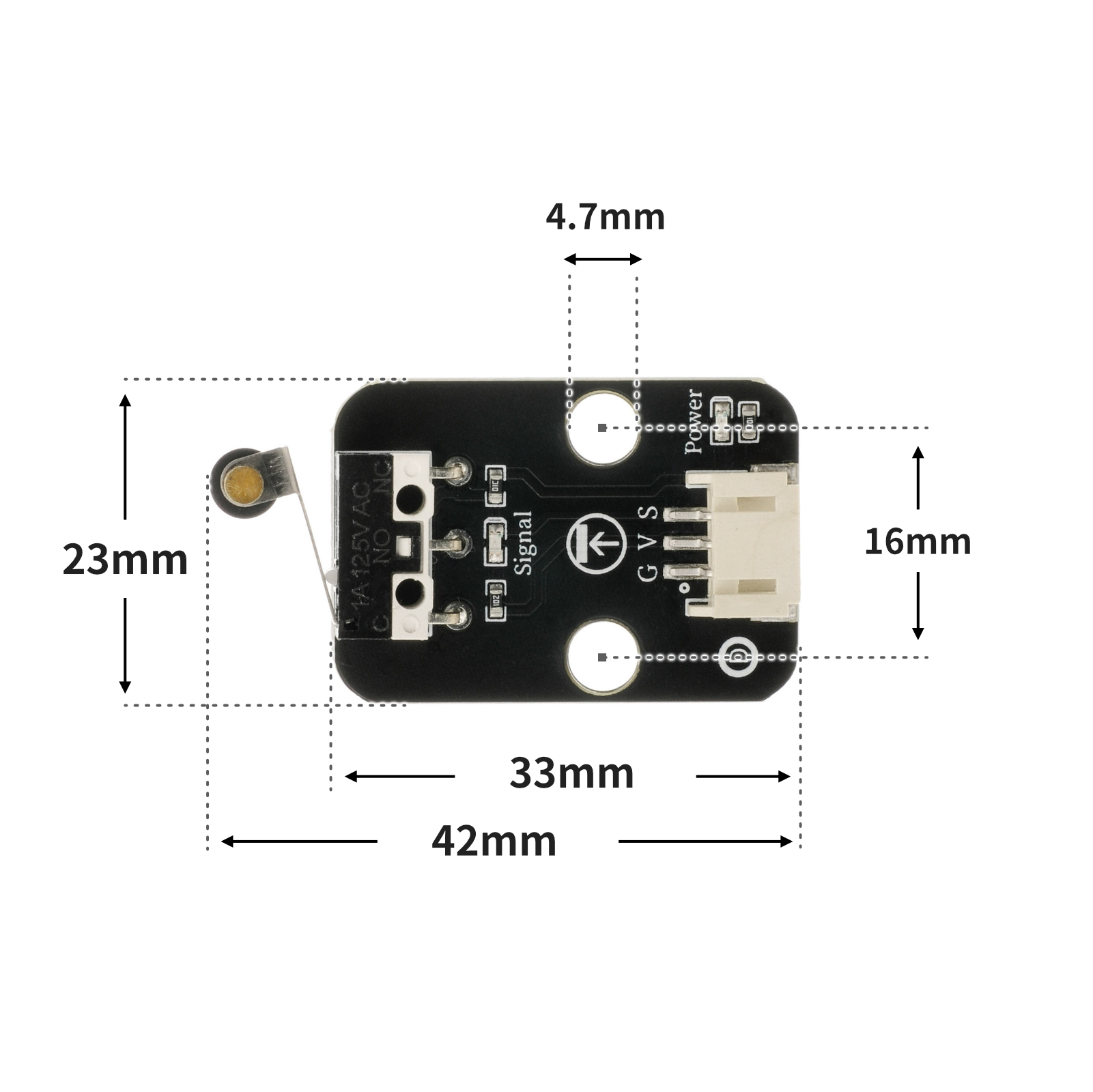
4, Circuit Board Size
5 of Arduino IDE example program
Arduino UNO Example (for Mixly IDE, Arduino IDE):
int limitswitchPin = 4;//设置碰撞开关接D4引脚
int led = 6;//设置led灯接D6引脚
void setup() {
Serial.begin(9600);//设置串口波特率
pinMode(limitswitchPin, INPUT);//设置碰撞开关为输入模式
pinMode(led, OUTPUT);//设置led为输出模式
}
void loop() {
//碰撞开关接uno开发板D4引脚;LED灯模块接D6引脚
if (digitalRead(limitswitchPin) == LOW) {//按下碰撞开关
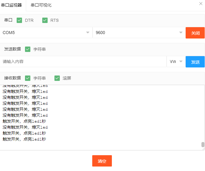
Serial.println("触发开关,点亮led1秒");
digitalWrite(led, HIGH);//点亮led
delay(1000);//延时1S
} else {
Serial.println("没有触发开关,熄灭led");
digitalWrite(led, LOW);//熄灭led
}
delay(500);
}ESP32 Python Example (for Mixly IDE / Micskit)
(Choose the Python ESP32 [ESP32 Generic(4MB)] to switch to code mode upload):
import machine
import time
pin2 = machine.Pin(2, machine.Pin.IN)
pin4 = machine.Pin(4, machine.Pin.OUT)
while True:
if pin2.value() == 0:
pin4.value(1)
time.sleep(1)
else:
pin4.value(0)
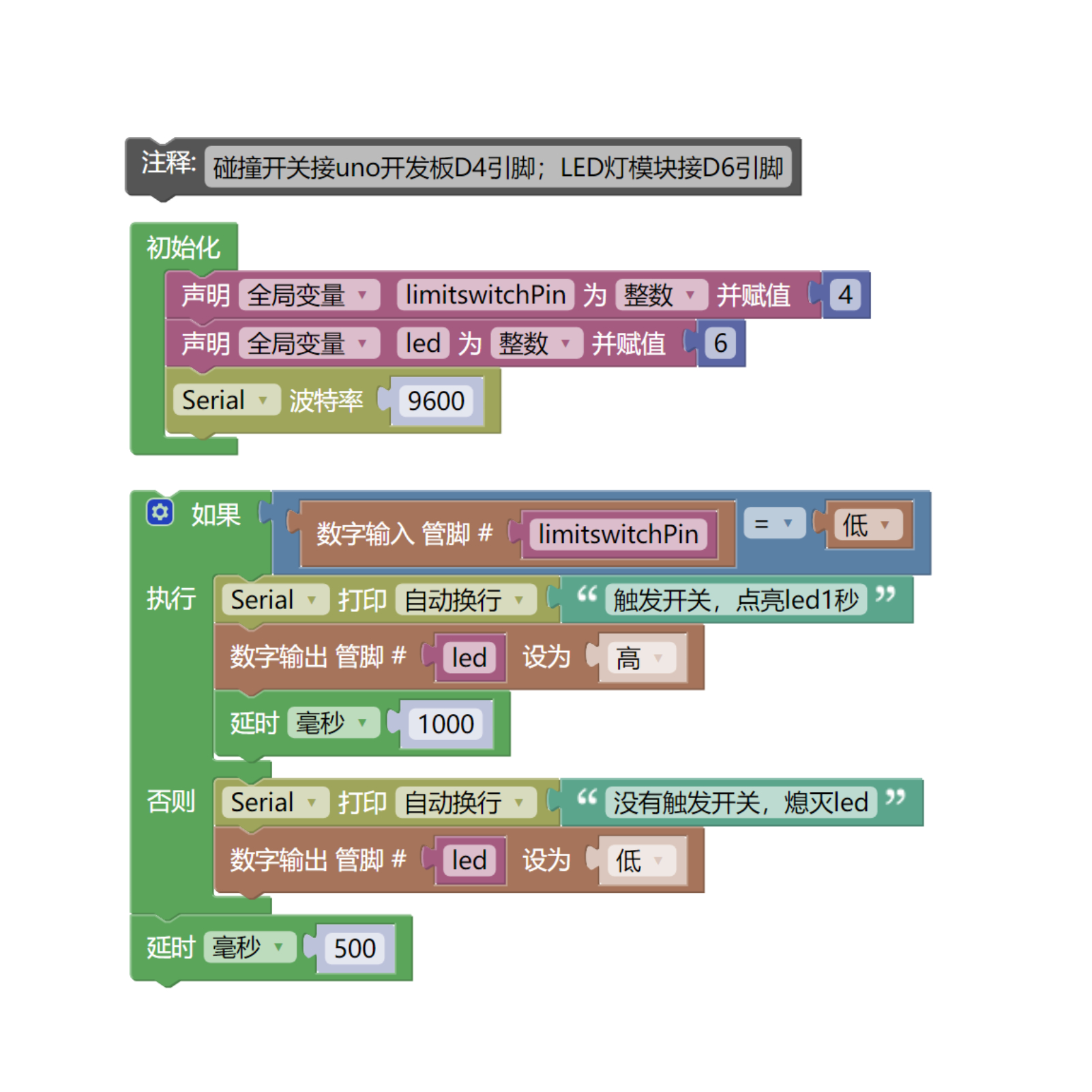
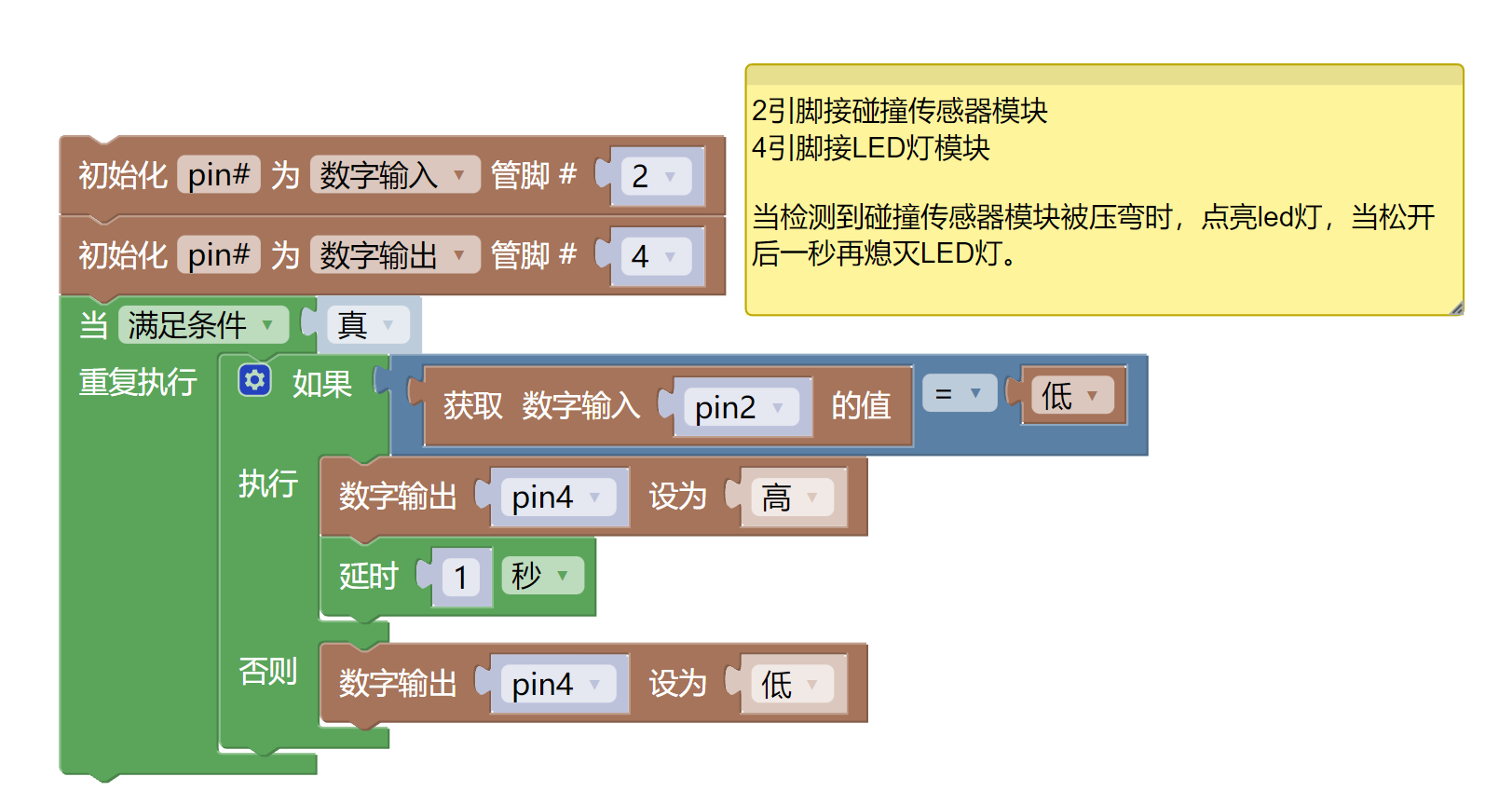
6, Miciqi Mixly Example Program (Graphical Language)
Arduino UNO Graphical Example Program:Click to download
ESP32 Python Graphical Example Program:Click to download
7, Test Environment Setup
Arduino UNO Test Environment Setup
Prepare Components:
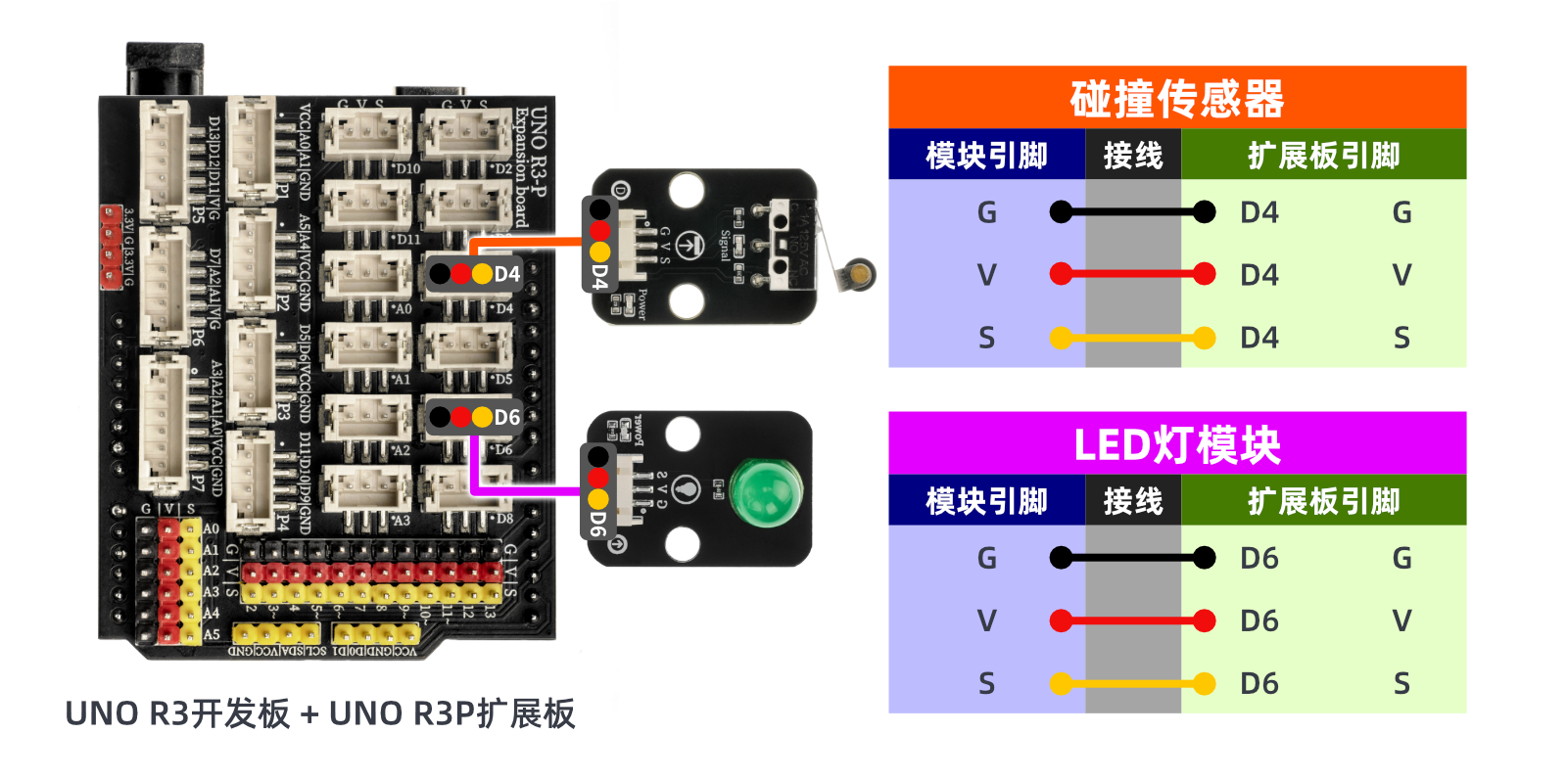
HELLO STEM UNO R3 DEVELOPMENT BOARD *1
HELLO STEM UNO R3 P EXPANSION BOARD *1
USB TYPE-C DATA CABLE *1
LED module (HS-F08L) *1
Collision Sensor Module (HS-S31L) *1
PH2.0 3P dual-head terminal line *2
Circuit wiring diagram:
ESP32 Python test environment setup
8. Video tutorial
Arduino UNO video tutorial:Click to view
ESP32 Python Video Tutorial:
9. Test conclusion
Arduino UNO Test Conclusion:
ESP32 Python test conclusion: