
1. Introduction
2. Schematic
Tapping Sensor-HS-S52P SchematicClick to view
Module Parameters
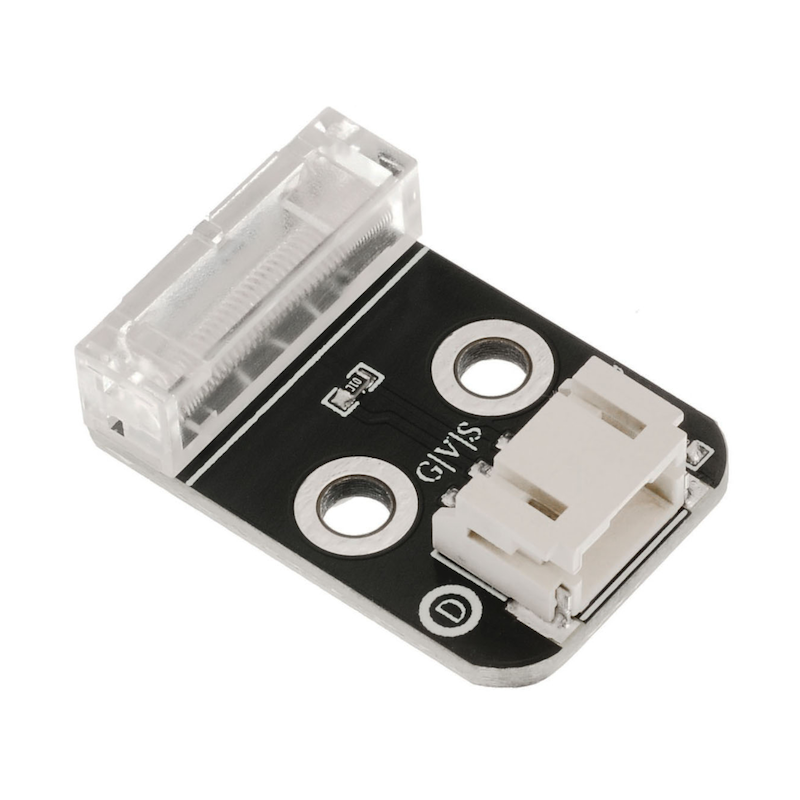
Pin Name | description |
|---|---|
G | GND (Negative Power Input) |
V | VCC (Positive Power Input) |
S | Digital Signal Pin |
Power Supply Voltage: 3.3V / 5V
Connection Method: PH2.0 Terminal Wire
Installation Method: Double Screw Fixed
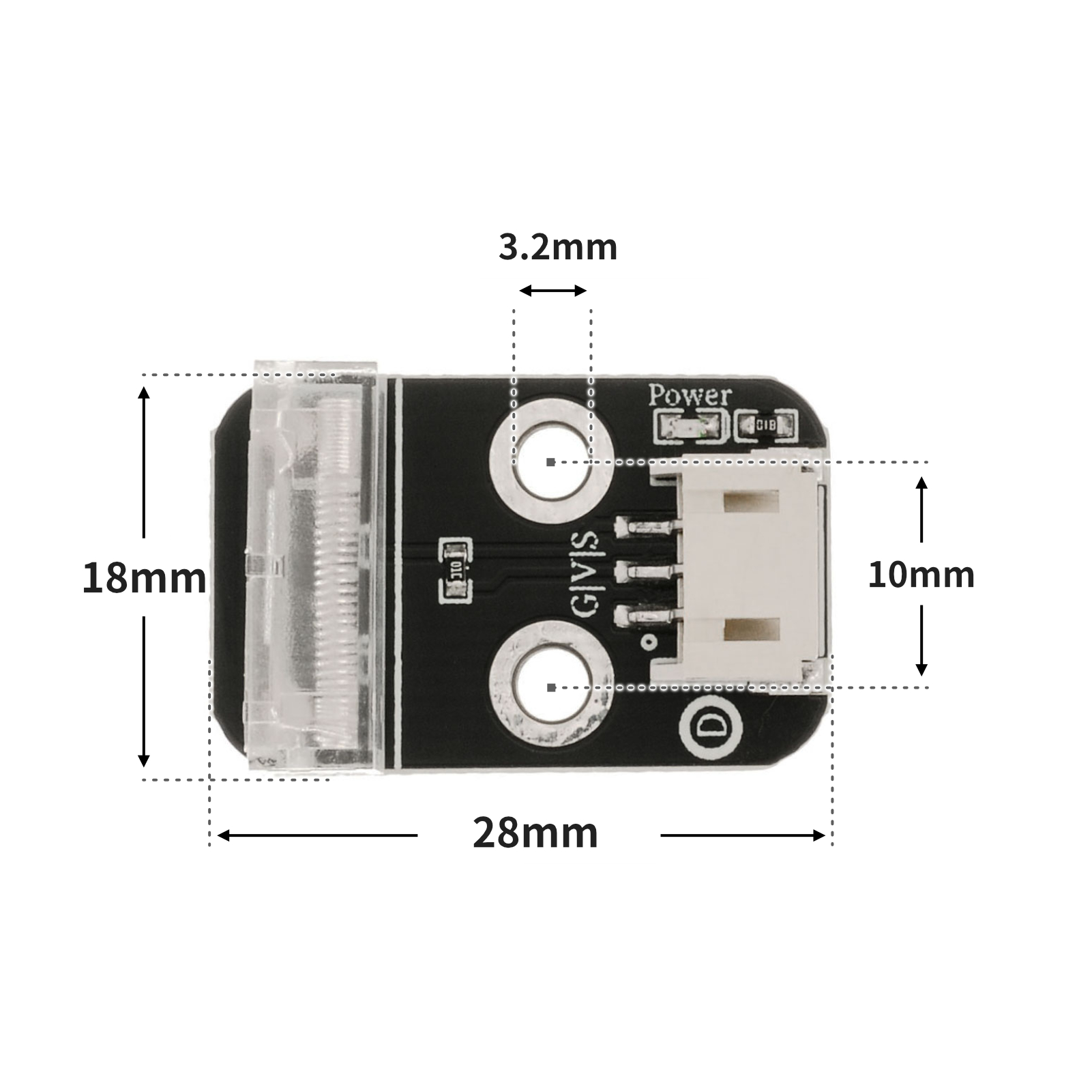
4, Circuit Board Size
5 of Arduino IDE example program
Attention: If prompted with an error message about the library file during program upload, please import the library file first!
Arduino IDE Library Download and Import Tutorial:Click to view
Example program (UNO development board):
void setup(){
  Serial.begin(9600);
  pinMode(A0, INPUT);
  pinMode(4, OUTPUT);
}

void loop(){
  //A0接敲击传感器,D4接led灯,晃动敲击传感器,led闪烁。
  if (digitalRead(A0) == 1) {
    Serial.println("未检测到冲击");
    digitalWrite(4,LOW);

  } else if (digitalRead(A0) == 0) {
    delay(300);
    digitalWrite(4,HIGH);
    Serial.println("传感器检测到冲击");
  }

}
6, ESP32 Python Example (for Mixly IDE/Misashi)
Choose the development board Python ESP32 [ESP32 Generic(4MB)] and upload in code mode
Attention: If prompted with an error message about the library file during program upload, please import the library file first!
Download and import tutorial for Mixly IDE ESP32 library:Click to view
Example program (ESP32-Python):
import machine
import time
pin2 = machine.Pin(2, machine.Pin.IN)
pin4 = machine.Pin(4, machine.Pin.OUT)
while True:
if pin2.value() == 1:
pin4.value(0)
print('未检测到冲击')
else:
pin4.value(1)
print('传感器检测到冲击')
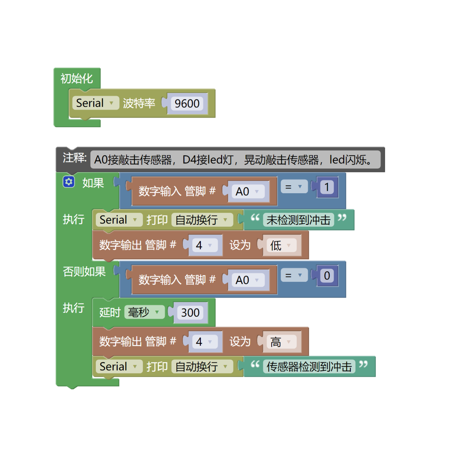
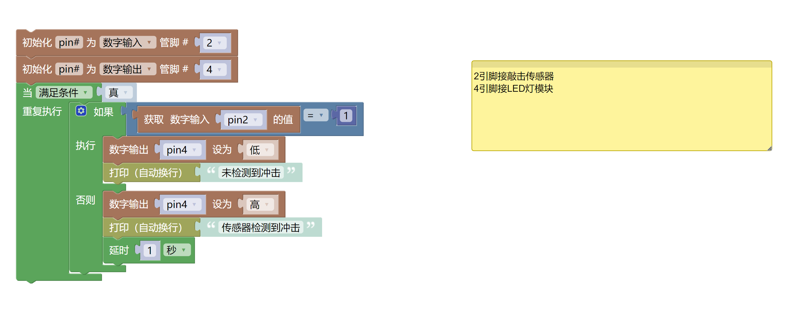
time.sleep(1)7, Mixly example program (graphical language)
Example program (UNO development board):Click to download
Attention: If prompted with an error message about the library file during program upload, please import the library file first!
Download and import tutorial of Mixly IDE Arduino library:Click to view
Example Program (ESP32 Development Board):Click to download
Attention: If prompted with an error message about the library file during program upload, please import the library file first!
Download and import tutorial for Mixly IDE ESP32 library:Click to view
8. Setting up the Test Environment
Arduino UNO Test Environment Setup
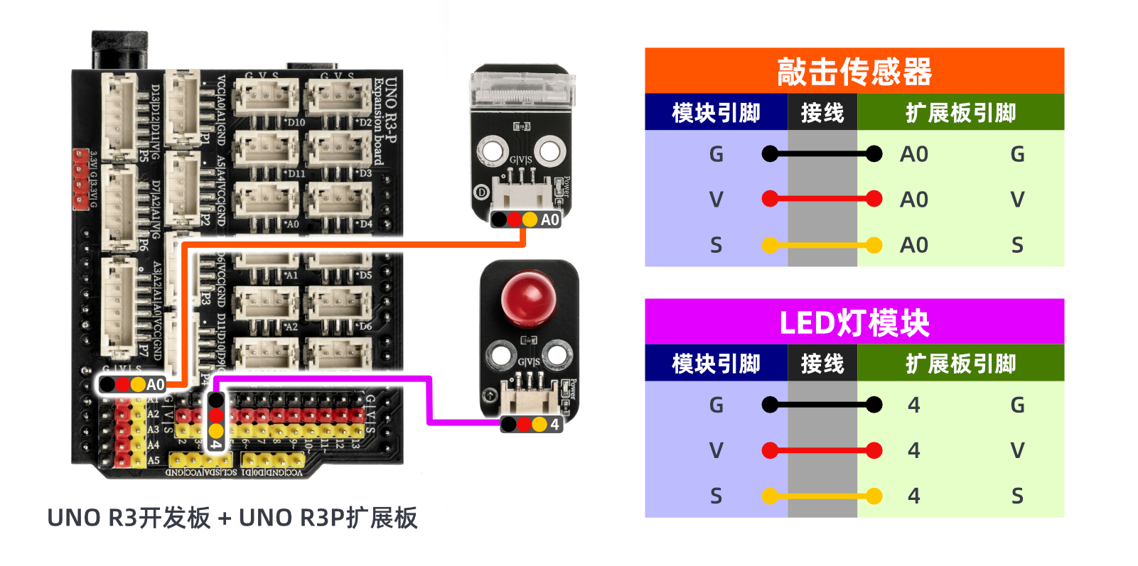
Prepare Components:
HELLO STEM UNO R3 DEVELOPMENT BOARD *1
HELLO STEM UNO R3P expansion board *1
USB TYPE-C DATA CABLE *1
Tapping sensor (HS-S52P) *1
LED light module (HS-F08P) *1
PH2.0 3P double-ended terminal line *2 or PH2.0 3P connector to DuPont wire *2
Circuit wiring diagram:
ESP32 Test Environment Setup
Prepare Components:Pending update...
Circuit wiring diagram:Pending update...
9, Video tutorial
Video tutorial:Click to view
10, Test results
Arduino UNO test results:
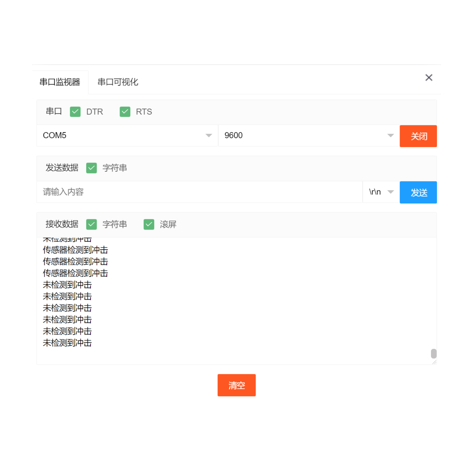
After the device is connected to the wire, burn the above program to the UNO-R3 PRO development board, and then connect the power supply.Open the serial port monitor, set the baud rate to 9600.When the sensor detects an impact signal, the input is low level (0), and the LED flashes and illuminates; otherwise, the LED extinguishes.
ESP32 Test Results:
Pending update...