1. Introduction
A digital tube, also known as a neon tube, is an electronic device capable of displaying numbers and other information.A glass tube includes an anode made of a metal wire mesh and multiple cathodes, most of the cathode shapes of the digital tube are in the form of numbers.To simplify the driving of the seven-segment display, the module uses a dedicated driver chip 74HC595A.The 74HC595A is an 8-bit serial input parallel output shift register chip.It can convert serial input data to parallel output, convenient for directly driving the segments of the digital tube.So it can be realized to control the brightness and extinction of the digital tube with only 2 master control IO ports.
2. Schematic
74HC595A one-digit digital tube-HS-F24-L schematicClick to view
Module Parameters
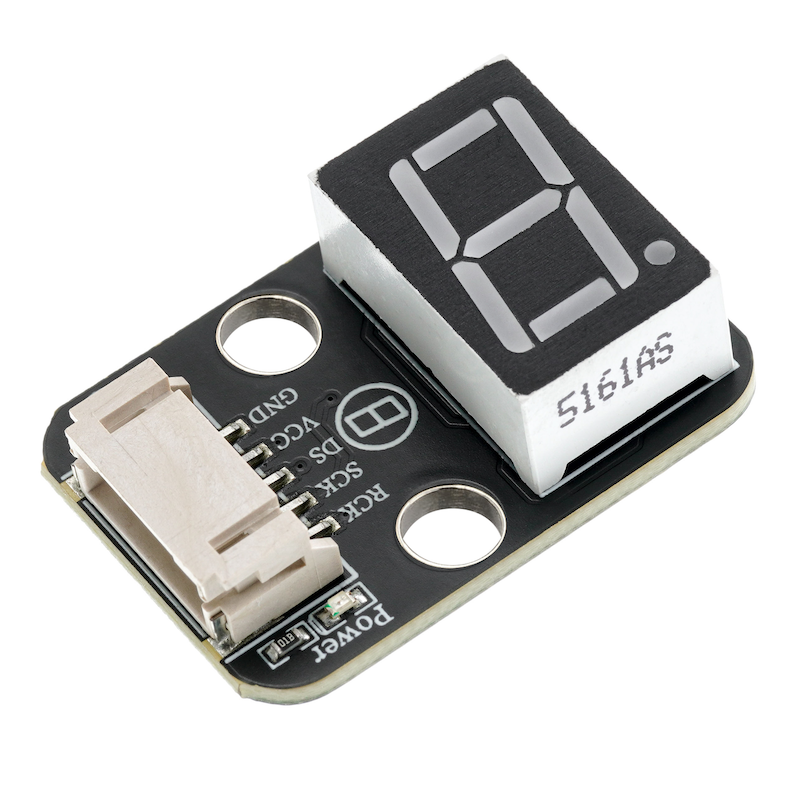
Pin Name | description |
|---|---|
GND | GND (power negative terminal) |
VCC | VCC (power positive terminal) |
DS | Serial data output pin |
SCK | Shift Register Clock Pin |
RCK | Storage Register Clock Input Pin |
Power Supply Voltage: 3.3V / 5V
Connection Method: PH2.0 2/3P
Installation method: Screw fixed / Lego construction
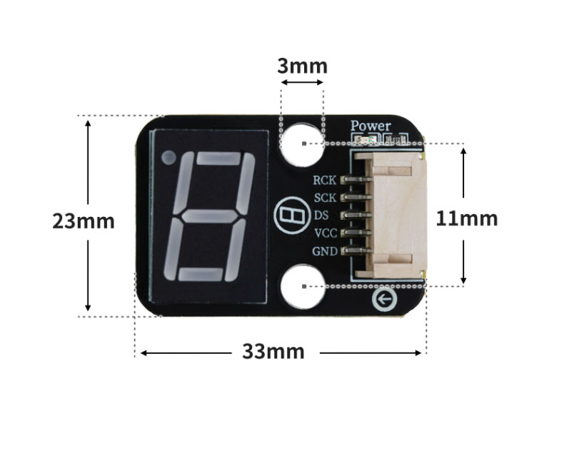
4, Circuit Board Size
5 of Arduino IDE example program
Attention: If prompted with an error message about the library file during program upload, please import the library file first!
Arduino IDE Library Download and Import Tutorial:Click to view
Example program (UNO development board):
#include "SCoop.h"
char mylist_1[11]={0xc0,0xf9,0xa4,0xb0,0x99,0x92,0x82,0xf8,0x80,0x90};
char mylist[11]={0x3f,0x06,0x5b,0x4f,0x66,0x6d,0x7d,0x07,0x7f,0x6f};
defineTask(scoopTask1)
void scoopTask1::setup()
{
}
void scoopTask1::loop()
{
for (int i = 0; i <= 9; i = i + (1)) {
shiftOut(6, 5, MSBFIRST, mylist_1[i]);
sleep(1000);
}
}
defineTask(scoopTask2)
void scoopTask2::setup()
{
}
void scoopTask2::loop()
{
//
for (int i = 0; i <= 9; i = i + (1)) {
digitalWrite(2,LOW);
shiftOut(A1, A2, MSBFIRST, mylist[i]);
digitalWrite(2,HIGH);
sleep(1000);
}
}
void setup(){
pinMode(6, OUTPUT);
pinMode(5, OUTPUT);
mySCoop.start();
pinMode(2, OUTPUT);
pinMode(A1, OUTPUT);
pinMode(A2, OUTPUT);
}
void loop(){
yield();
// HS-F23-L采用共阴数码管
// HS-F24-L采用共阳数码管
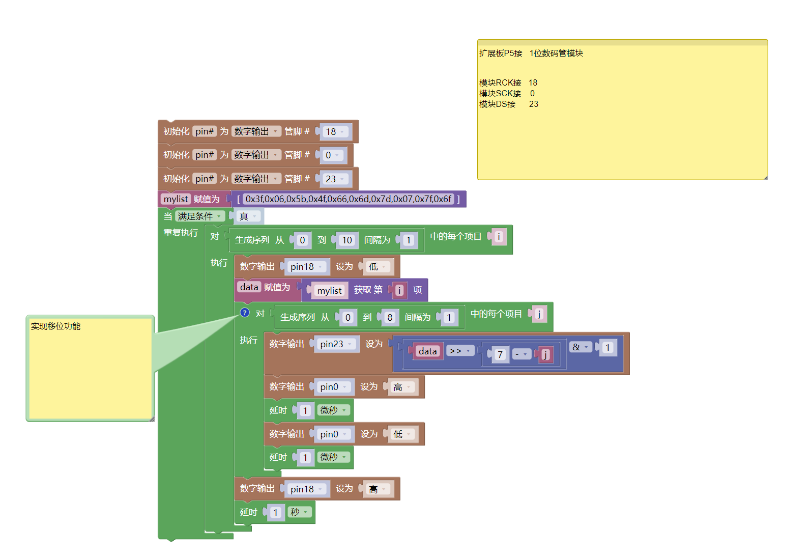
}6, ESP32 Python Example (for Mixly IDE/Misashi)
Choose the development board Python ESP32 [ESP32 Generic(4MB)] and upload in code mode
Attention: If prompted with an error message about the library file during program upload, please import the library file first!
Download and import tutorial for Mixly IDE ESP32 library:Click to view
Example program (ESP32-Python):
import machine
import time
pin18 = machine.Pin(18, machine.Pin.OUT)
pin0 = machine.Pin(0, machine.Pin.OUT)
pin23 = machine.Pin(23, machine.Pin.OUT)
mylist = [0x3f,0x06,0x5b,0x4f,0x66,0x6d,0x7d,0x07,0x7f,0x6f]
while True:
for i in range(0, 10, 1):
pin18.value(0)
data = mylist[i]
# 实现移位功能
for j in range(0, 8, 1):
pin23.value(((data>>(7 - j))&1))
pin0.value(1)
time.sleep_us(1)
pin0.value(0)
time.sleep_us(1)
pin18.value(1)
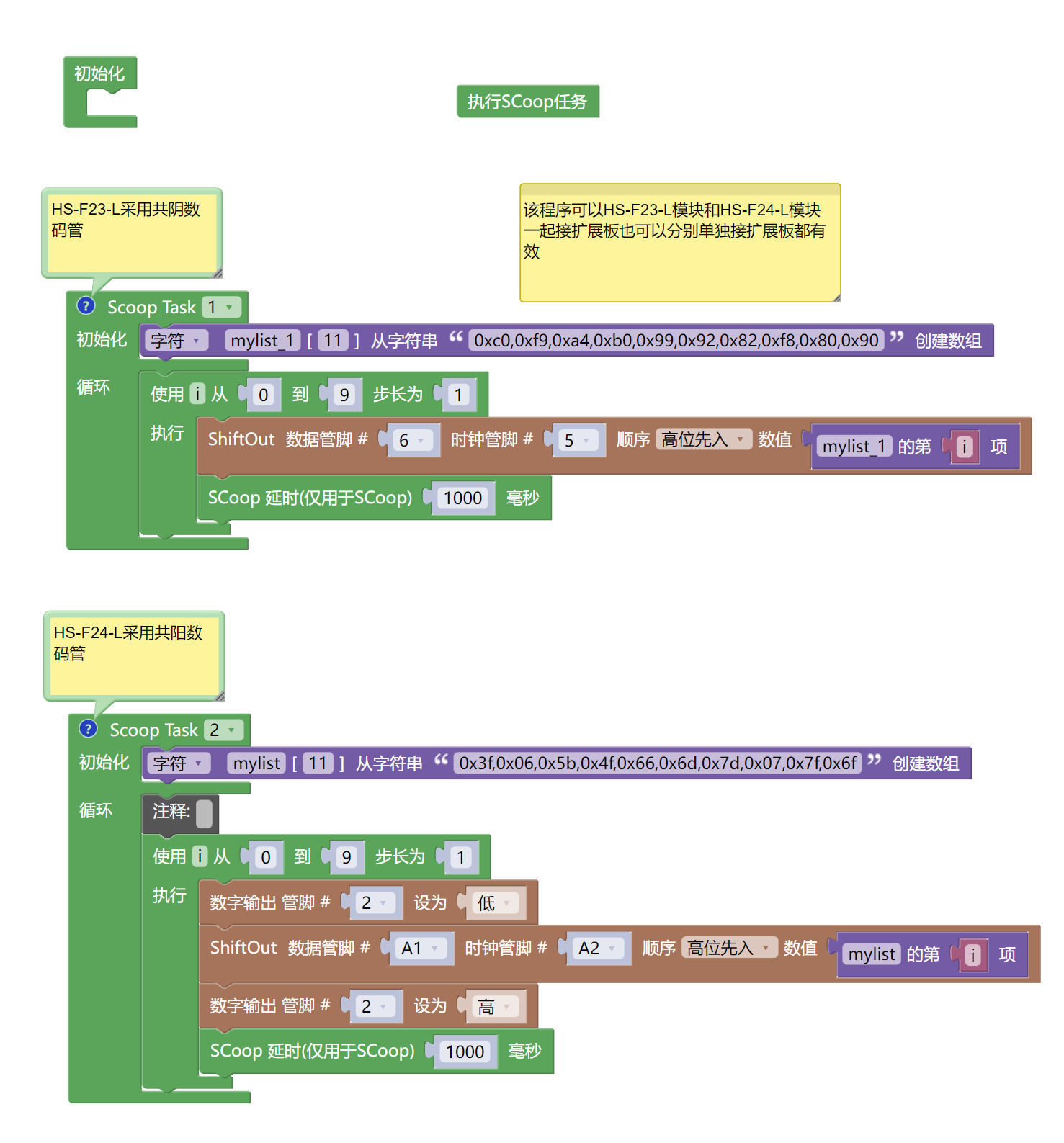
time.sleep(1)7, Mixly example program (graphical language)
Example program (UNO development board):Click to download
Attention: If prompted with an error message about the library file during program upload, please import the library file first!
Download and import tutorial of Mixly IDE Arduino library:Click to view
Example Program (ESP32 Development Board):Click to download
Attention: If prompted with an error message about the library file during program upload, please import the library file first!
Download and import tutorial for Mixly IDE ESP32 library:Click to view
8. Setting up the Test Environment
Arduino UNO Test Environment Setup
Prepare Components:
HELLO STEM UNO R3 PRO DEVELOPMENT BOARD *1
R3P expansion board *1
USB TYPE-C DATA CABLE *1
1-Digit Decimal Tube (HS-F24-L) *1
PH2.0 5P dual-head terminal line *1 or PH2.0 5P terminal to DuPont wire *1
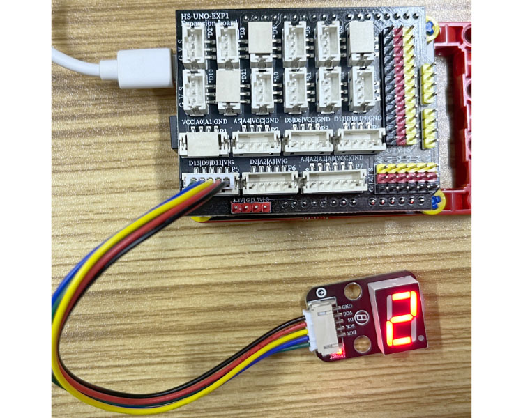
Circuit wiring diagram:
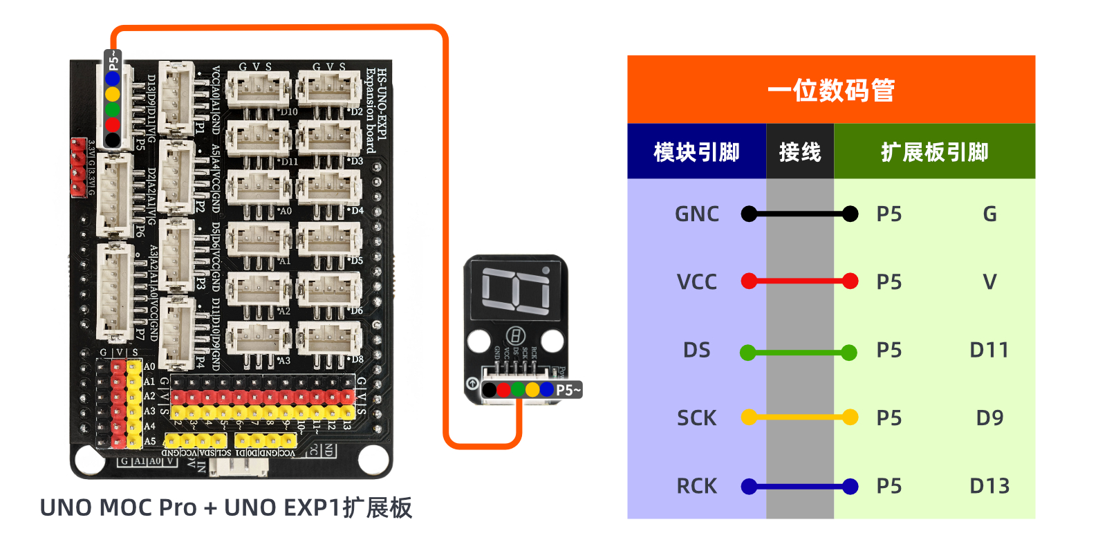
ESP32 Test Environment Setup
Prepare Components:Pending update...
Circuit wiring diagram:Pending update...
9, Video tutorial
Video tutorial:Click to view
10, Test results
Arduino UNO test results:
After the device is connected to the wire, the above program is burned to the UNO-R3 PRO development board, and then the power is turned on. After that, you can observe the digital tube starting to count.