
1. Introduction
2. Schematic
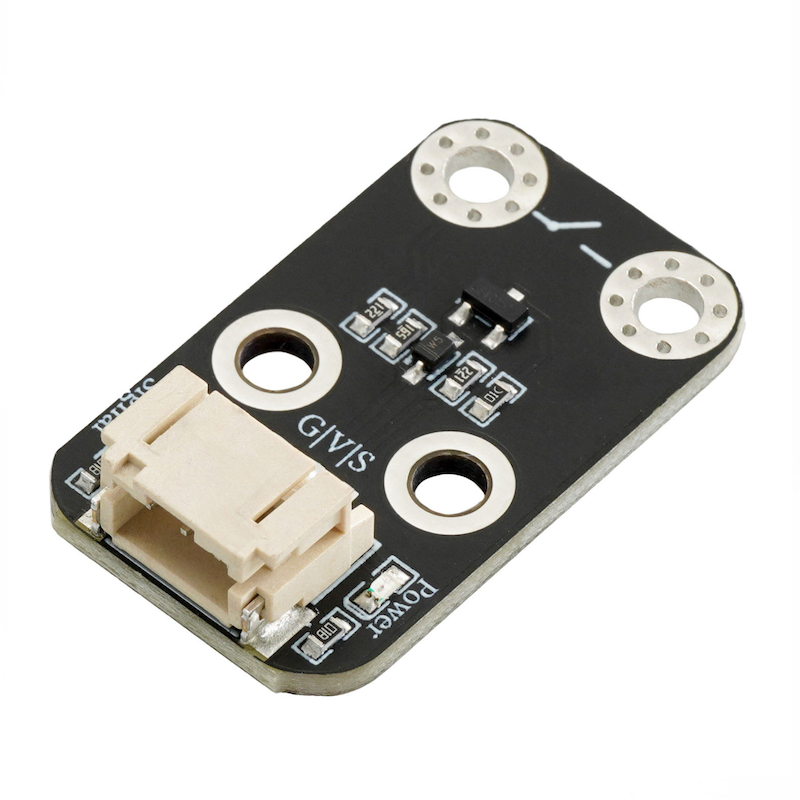
HS-S67P Conductivity Switch Module SchematicClick to view
Module Parameters
Pin Name | description |
|---|---|
G | GND (Negative Power Input) |
V | VCC (Positive Power Input) |
S | Digital Signal Pin |
Power Supply Voltage: 3.3V / 5V
Connection method: PH2.0 terminal wire
Installation method: Screw fixed
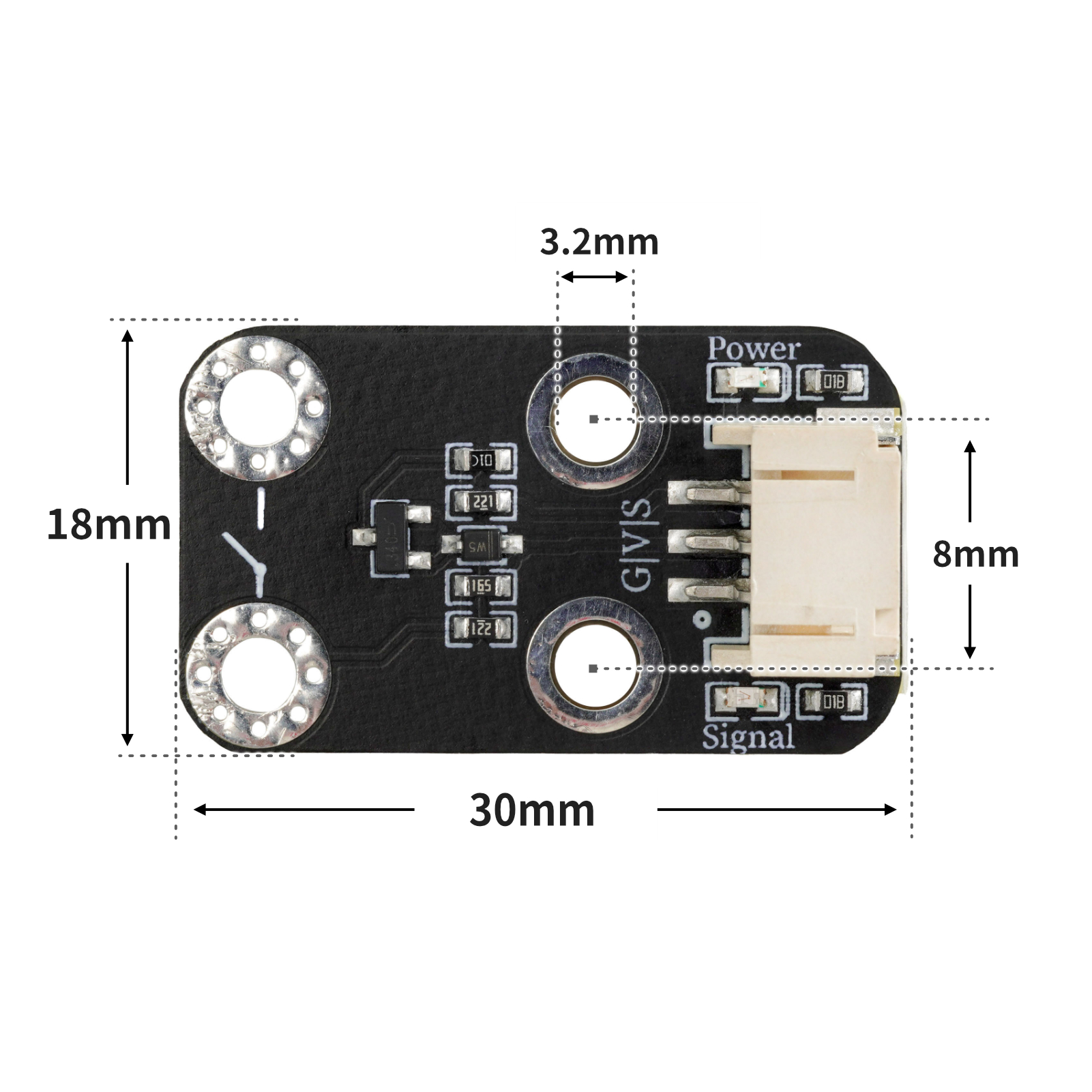
4, Circuit Board Size
5 of Arduino IDE example program
Attention: If prompted with an error message about the library file during program upload, please import the library file first!
Arduino IDE Library Download and Import Tutorial:Click to view
Example program (UNO development board):
void setup(){
  Serial.begin(9600);
  pinMode(4, INPUT);
  pinMode(9, OUTPUT);
}

void loop(){
  //有源蜂鸣器模块接UNO开发板D9,电导开关模块接UNO开发板D4;
  //电导开关模块在连接到导体时,会产生一个高电平(1),使蜂鸣器响起;
  //当未检测到导体连接时,蜂鸣器不响。
  if (digitalRead(4) == 1) {
    digitalWrite(9,HIGH);
    Serial.println(String("导体连接:") + String(digitalRead(4)));

  } else if (digitalRead(4) == 0) {
    Serial.println(String("断开:") + String(digitalRead(4)));
    digitalWrite(9,LOW);
  }

}
6, ESP32 Python Example (for Mixly IDE/Misashi)
Choose the development board Python ESP32 [ESP32 Generic(4MB)] and upload in code mode
Attention: If prompted with an error message about the library file during program upload, please import the library file first!
Download and import tutorial for Mixly IDE ESP32 library:Click to view
Example program (ESP32-Python):
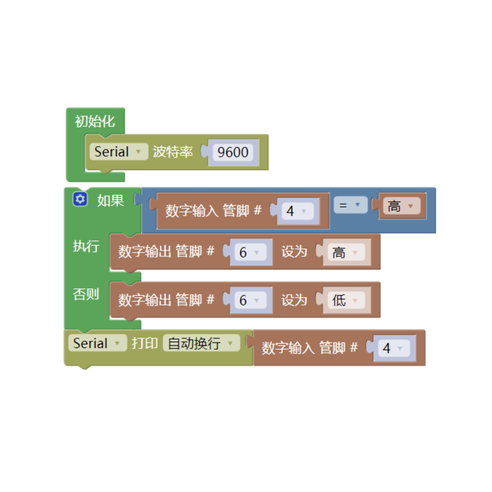
待更新...7, Mixly example program (graphical language)
Example program (UNO development board):Click to download
Attention: If prompted with an error message about the library file during program upload, please import the library file first!
Download and import tutorial of Mixly IDE Arduino library:Click to view
Example Program (ESP32 Development Board):Click to download
Attention: If prompted with an error message about the library file during program upload, please import the library file first!
Download and import tutorial for Mixly IDE ESP32 library:Click to view
Image pending update...
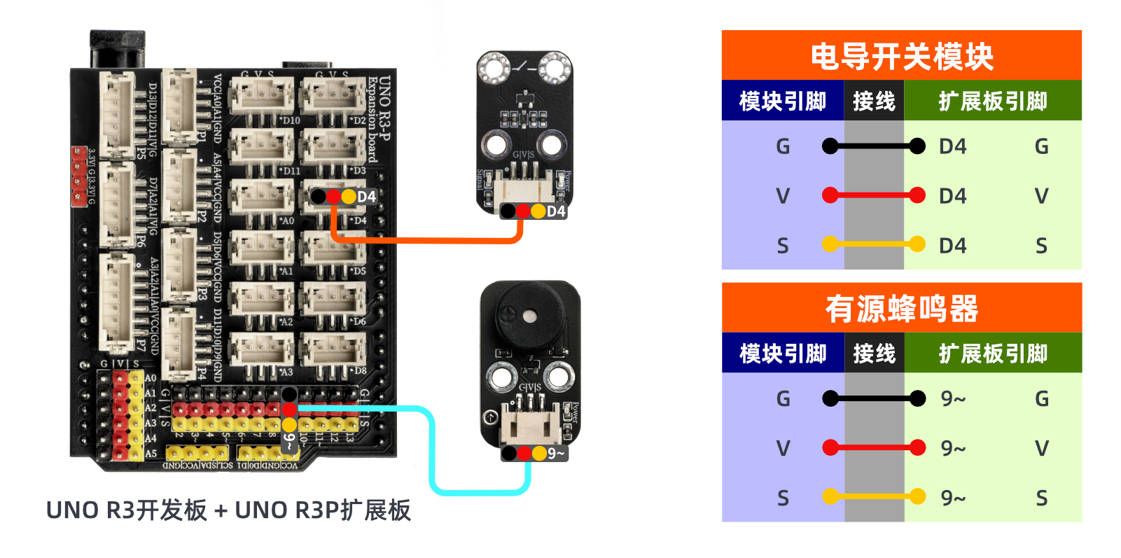
8. Setting up the Test Environment
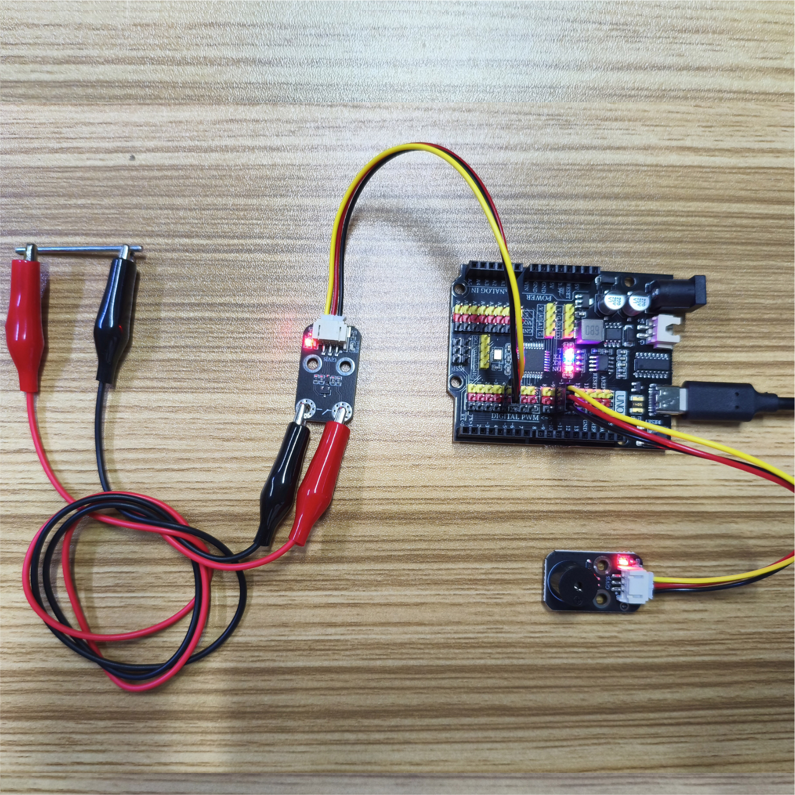
Arduino UNO Test Environment Setup
Prepare Components:
HELLO STEM UNO R3 DEVELOPMENT BOARD *1
HELLO STEM UNO R3 P EXPANSION BOARD *1
USB TYPE-C DATA CABLE *1
Active buzzer module (HS-F07P) *1
Conductivity switch module (HS-67P) *1
PH2.0 3P terminal to DuPont wire *2 or PH2.0 3P dual-head terminal wire *2
Circuit wiring diagram:
ESP32 Test Environment Setup
Prepare Components:Pending update...
Circuit wiring diagram:Pending update...
9, Video tutorial
Video tutorial:Click to view
10, Test results
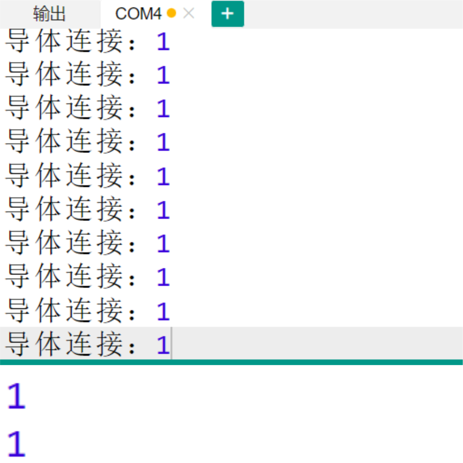
Arduino UNO test results:
After the device is connected and the program is uploaded to the Arduino UNO development board, you will find that the buzzer sounds when the conductivity switch module is connected to the conductor; otherwise, the buzzer does not sound.
ESP32 Test Results:
Pending update...