1. Introduction
2. Schematic
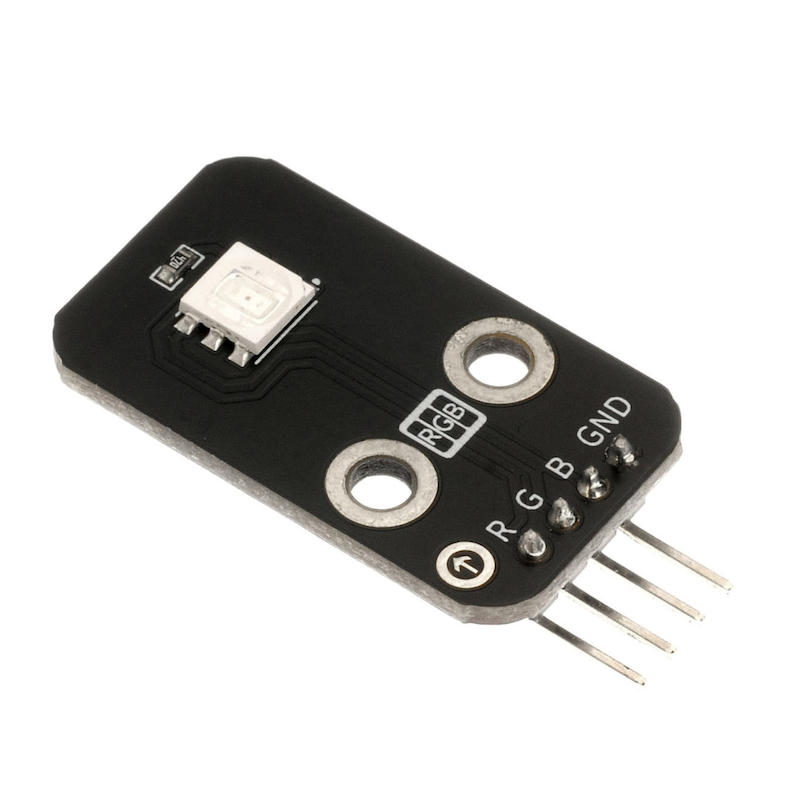
Schematic of RGBLED-HS-F01AClick to view
Module Parameters
Pin Name | description |
|---|---|
GND | GND (Negative Power Input) |
B | Digital Signal Pin |
R | Digital Signal Pin |
G | Digital Signal Pin |
Power Supply Voltage: 3.3V / 5V
Connection Type: 2.54mm Header
Installation Method: Double Screw Fixed
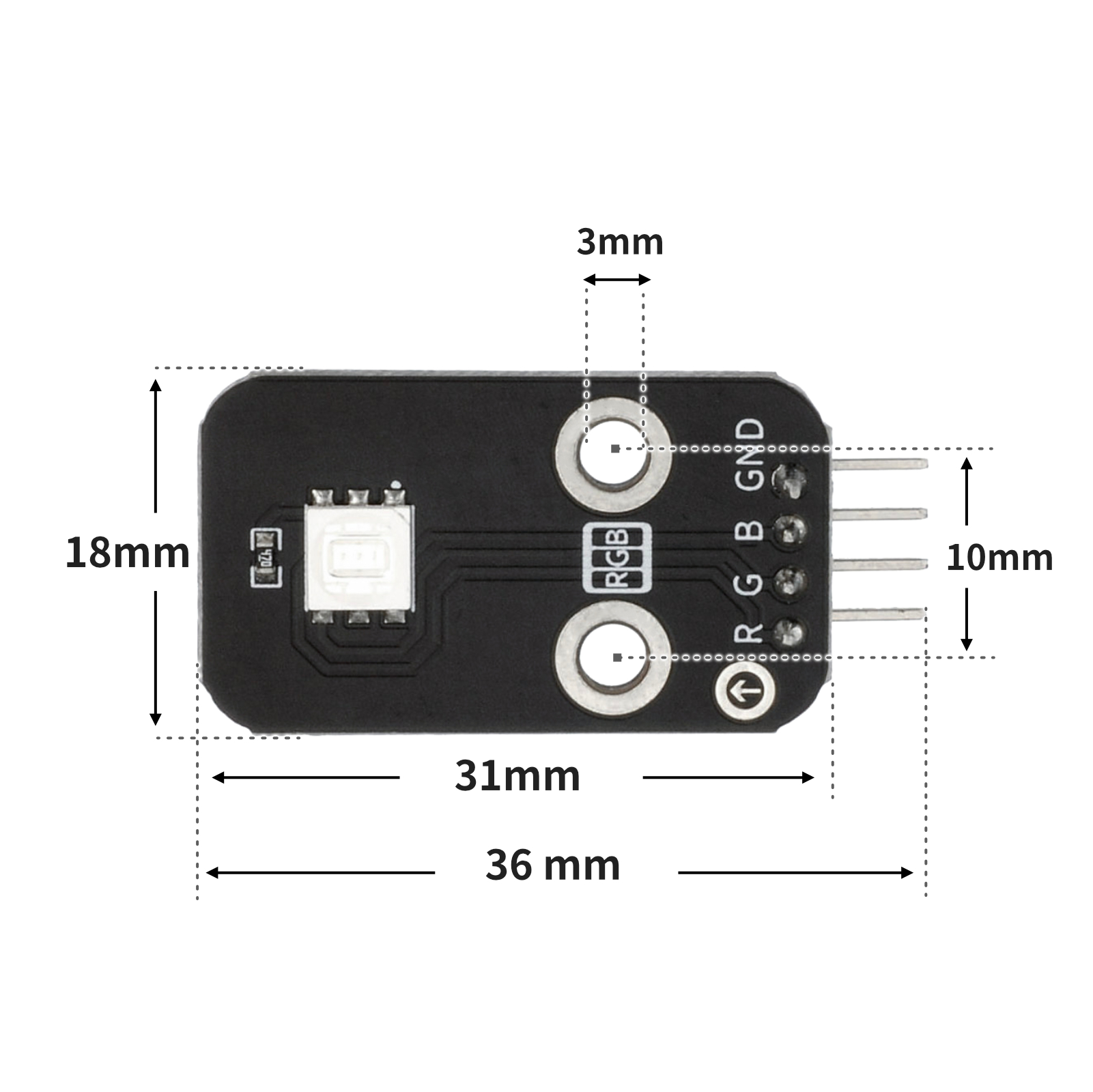
4, Circuit Board Size
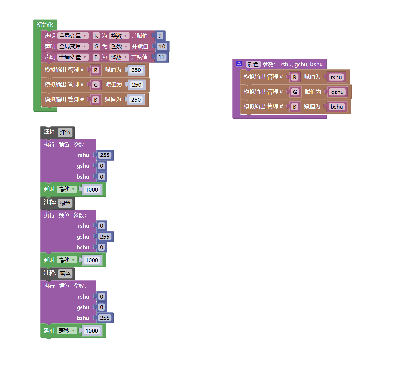
5 of Arduino IDE example program
Attention: If prompted with an error message about the library file during program upload, please import the library file first!
Arduino IDE Library Download and Import Tutorial:Click to view
Example program (UNO development board):
/***********************************************************
文件名:15_RGB_led.ino
描述:实现RGB led灯颜色的切换。
作者:陈志强
日期:2022.11.10
***********************************************************/
//RGB led 模块RGB分别引脚接D9,D10,D11口,GND引脚接控制板GND
int R = 9;//定义数字常量,RGB led 模块R接9口
int G = 10;//定义数字常量,RGB led 模块G接10口
int B = 11;//定义数字常量,RGB led 模块B接11口
void RGB_Value(int rshu, int gshu, int bshu) {//亮灯函数
analogWrite(R, rshu);
analogWrite(G, gshu);
analogWrite(B, bshu);
}
void setup() {
RGB_Value(0, 0, 0);//灯熄灭
}
void loop() {
RGB_Value(255, 0, 0);//亮红色
delay(1000);//延时1s
RGB_Value(0, 255, 0);//亮绿色
delay(1000);//延时1s
RGB_Value(0, 0, 255);//亮蓝色
delay(1000);//延时1s
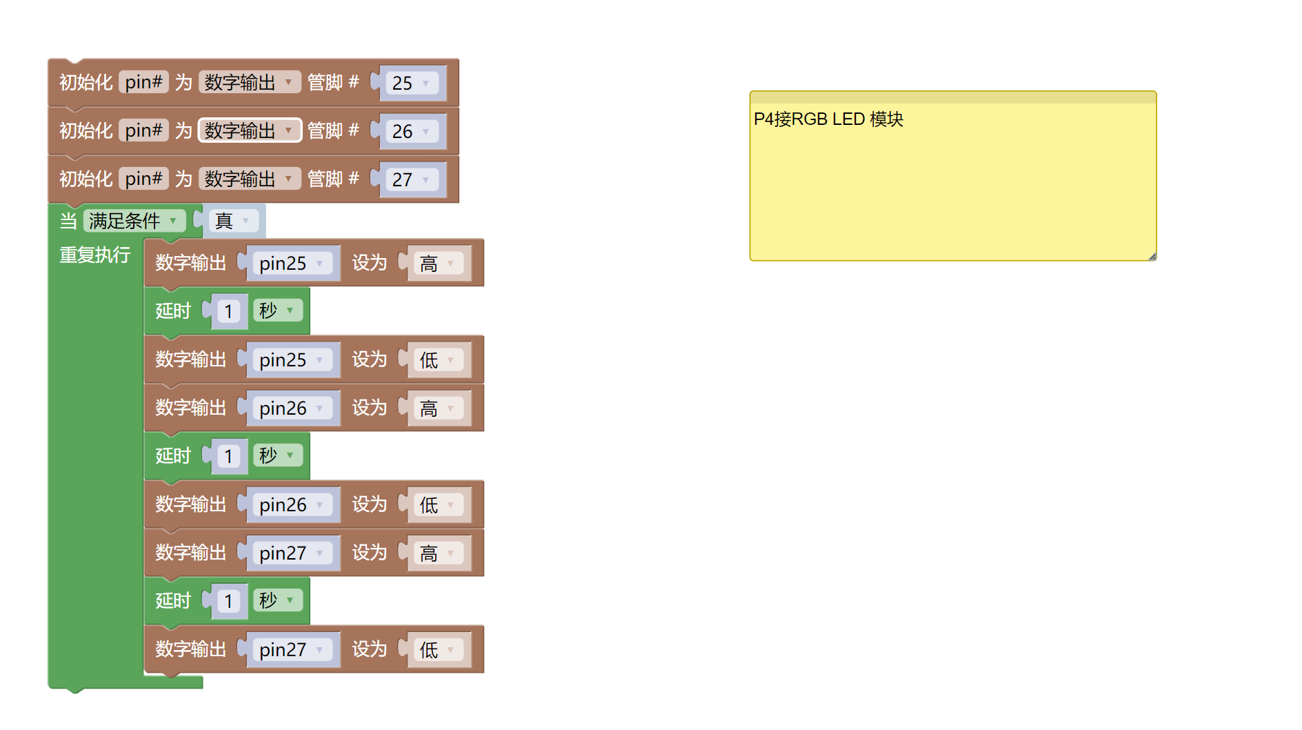
}6, ESP32 Python Example (for Mixly IDE/Misashi)
Choose the development board Python ESP32 [ESP32 Generic(4MB)] and upload in code mode
Attention: If prompted with an error message about the library file during program upload, please import the library file first!
Download and import tutorial for Mixly IDE ESP32 library:Click to view
Example program (ESP32-Python):
import machine
import time


pin25 = machine.Pin(25, machine.Pin.OUT)
pin26 = machine.Pin(26, machine.Pin.OUT)
pin27 = machine.Pin(27, machine.Pin.OUT)
while True:
    pin25.value(1)
    time.sleep(1)
    pin25.value(0)
    pin26.value(1)
    time.sleep(1)
    pin26.value(0)
    pin27.value(1)
    time.sleep(1)
    pin27.value(0)
7, Mixly example program (graphical language)
Example program (UNO development board):Click to download
Attention: If prompted with an error message about the library file during program upload, please import the library file first!
Download and import tutorial of Mixly IDE Arduino library:Click to view
Example Program (ESP32 Development Board):Click to download
Attention: If prompted with an error message about the library file during program upload, please import the library file first!
Download and import tutorial for Mixly IDE ESP32 library:Click to view
8. Setting up the Test Environment
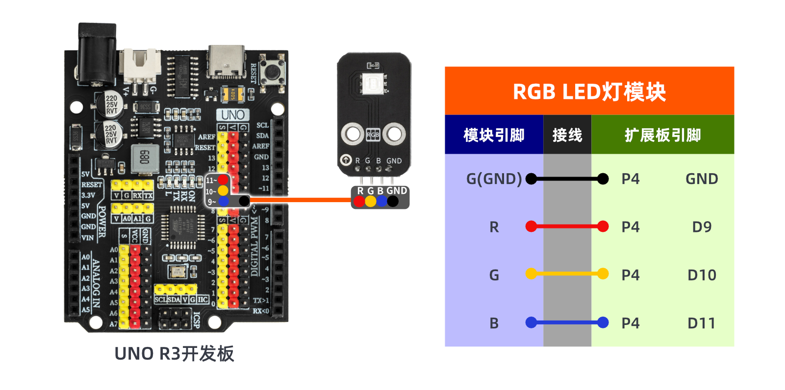
Arduino UNO Test Environment Setup
Prepare Components:
HELLO STEM UNO R3 PRO DEVELOPMENT BOARD *1
USB TYPE-C DATA CABLE *1
RGB LED module (HS-F01A) *1
1P female-to-female DuPont wire *4 pieces or 3P female-to-female DuPont wire, 1P female-to-female DuPont wire each *1 piece
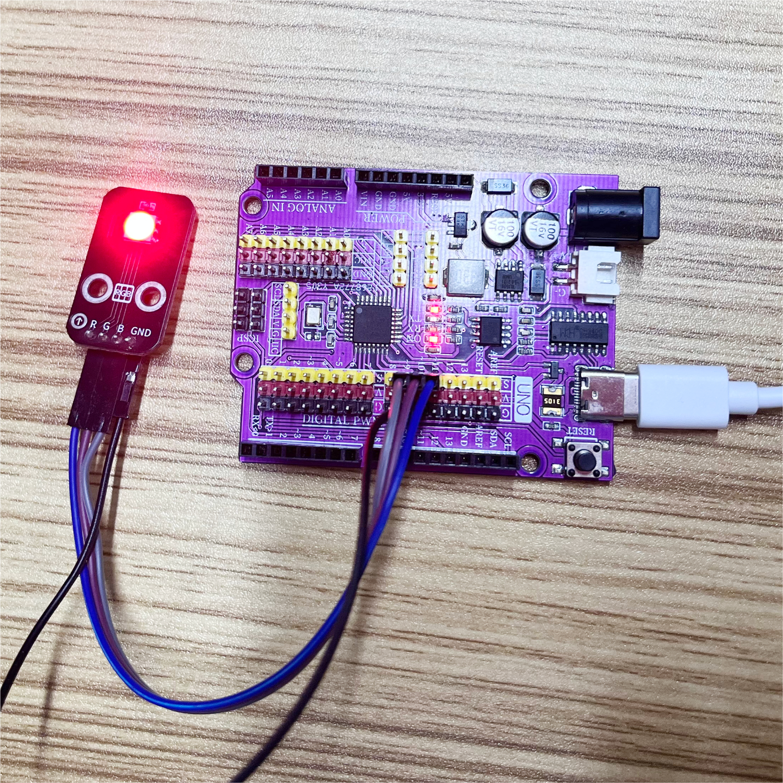
Circuit wiring diagram:
ESP32 Test Environment Setup
Prepare Components:Pending update...
Circuit wiring diagram:Pending update...
9, Video tutorial
Video tutorial:Click to view
10, Test results
Arduino UNO test results:
After the device is connected to the wires, burn the above program to the Arduino UNO development board, and then proceed with the color ratio according to the above ratio chart.We can see the RGB LED light change colors every second (red, green, blue).