1. Introduction
The I2C digital power meter is a high-resolution, high-precision, large-range measurement module that can measure the voltage, current, and power of various electronic modules and electrical equipment within 26V 8A, with a maximum relative error not exceeding ±0.2% (it requires a simple manual calibration before use).Can be used for power consumption measurement of solar systems, battery coulomb meters, motors, main control boards, or electronic modules, as well as for battery endurance evaluation and real-time online monitoring of power parameters.The module uses TI INA219 zero-drift current/power monitoring chip and a 2W high-power low-drift 10mΩ alloy sampling resistor, with voltage and current resolutions of up to 4mV and 1mA respectively. Under full-scale measurement conditions, the maximum relative measurement error of voltage and current does not exceed ±0.2%, and provides 4 I2C addresses that can be configured via a dip switch.The module can accurately measure bidirectional high-side current (the current flowing through the power source or the positive pole of the battery), which is particularly useful in solar or coulomb counter applications where the battery needs to be charged and discharged, the user can understand the charging and discharging state of the battery through the positive and negative readings of the current, and also understand the real-time voltage, current, and power of the battery's charging and discharging.In motor application scenarios, it is possible to monitor the motor current in real time to determine if the current is too high due to stall or overloading, and take protective measures in a timely manner.In addition, this module can also be used to measure the real-time power consumption of various electronic modules or the entire project, thereby assessing the battery life.
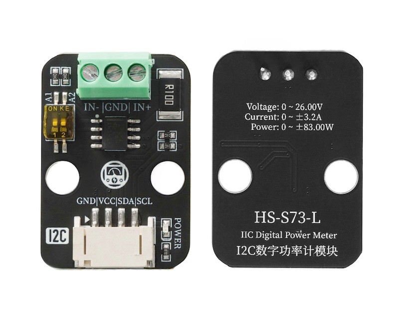
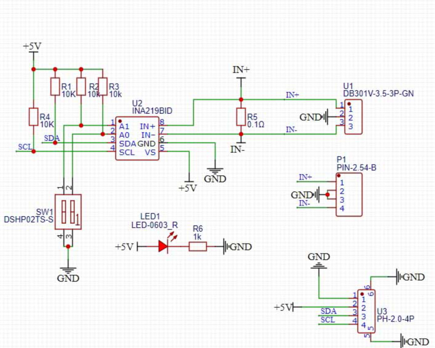
2. Schematic
Module Parameters
Pin Name | description |
|---|---|
G | GND (Negative Power Input) |
V | VCC (Positive Power Input) |
SDA | Data pin |
SCL | clock pin |
Supply voltage: 3.3V-5V
Connection method: PH2.0 4P terminal wire
Installation method: Modular fixed
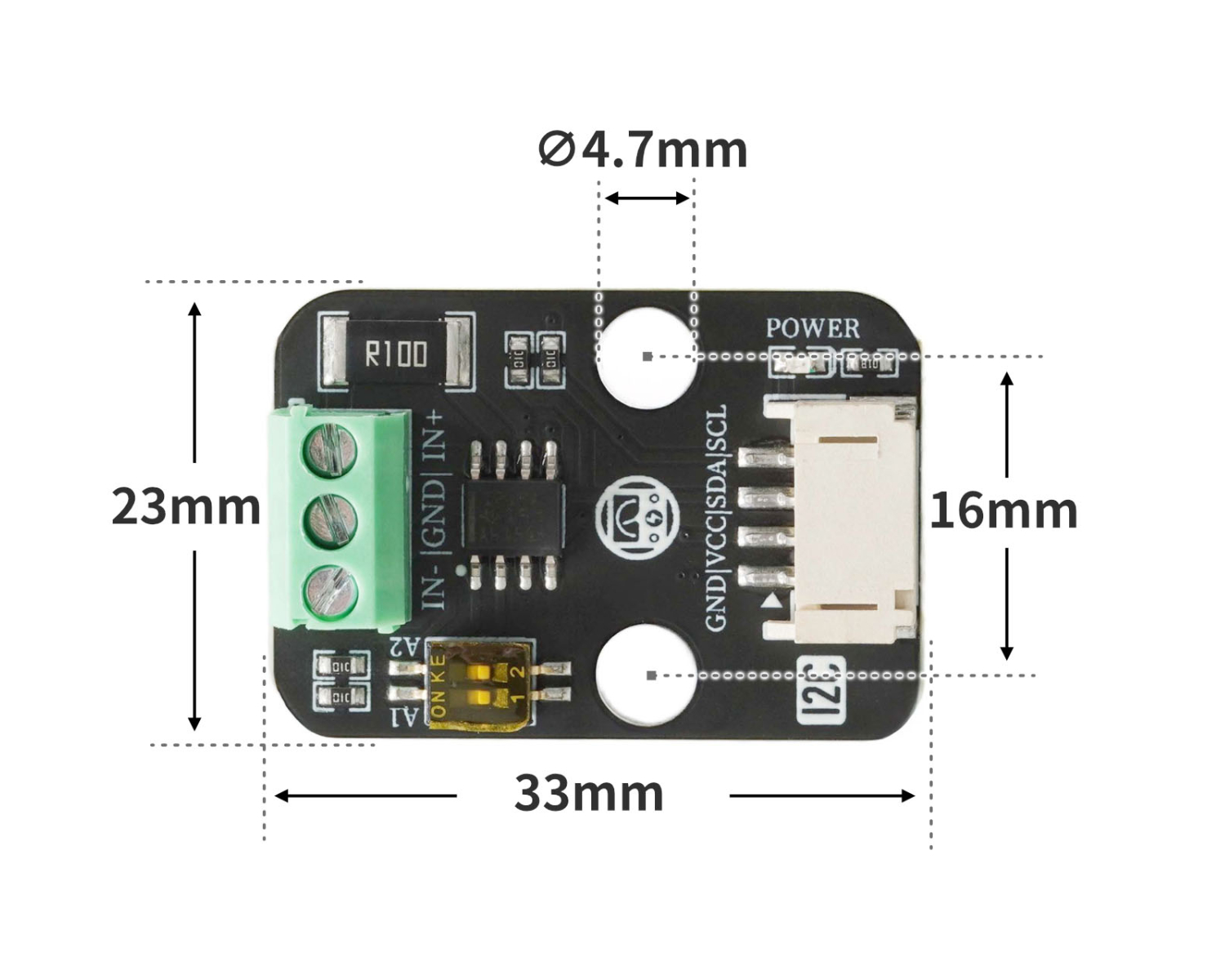
4, Circuit Board Size
Add Arduino Library File
Reference here if you don't know how to use library files:Install and use library files
Download library files: Click to download
Installation steps for the MiQi UNO development board library (download and install the MiQi library before using the code):Reference link
6, Add MicroPython environment library file
MiXin ESP32 development board library download and installation steps (download and install the MiXin library before using the code):Reference link
7. Arduino IDE example program
Example Program (UNO Development Board): Click to Download
#include "DFRobot_INA219.h"
#include <Wire.h>

DFRobot_INA219_IIC     ina219(&Wire, INA219_I2C_ADDRESS4);

float ina219Reading_mA = 1000;
float extMeterReading_mA = 1000;

void setup(){

  while (!ina219.begin()) {
    Serial.println("INA219 初始化失败:请检查I2C接线/地址是否正确");
    delay(1000);
  }

  ina219.linearCalibrate(ina219Reading_mA, extMeterReading_mA);
  Serial.begin(9600);
}

void loop(){
  Serial.println(String("总线电压:") + String(ina219.getBusVoltage_V()));
  Serial.println(String("分流电压:") + String(ina219.getShuntVoltage_mV()));
  Serial.println(String("电流值:") + String(ina219.getCurrent_mA()));
  Serial.println(String("功率值") + String(ina219.getPower_mW()));
  Serial.println(String("------------------"));
  delay(500);

}
ESP32 Python Example (for Mixly IDE / Micskit)
(Choose the Python ESP32 [ESP32 Generic(4MB)] to switch to code mode upload):
from machine import I2C, Pin
import time

INA219_REG_CONFIG        = 0x00
INA219_REG_SHUNTVOLTAGE  = 0x01
INA219_REG_BUSVOLTAGE    = 0x02
INA219_REG_POWER         = 0x03
INA219_REG_CURRENT       = 0x04
INA219_REG_CALIBRATION   = 0x05

INA219_CONFIG_RESET      = 0x8000
INA219_I2C_ADDRESS1      = 0x40
INA219_I2C_ADDRESS2      = 0x41
INA219_I2C_ADDRESS3      = 0x44
INA219_I2C_ADDRESS4      = 0x45

class eIna219BusVolRange_t:
    eIna219BusVolRange_16V = 0x0000
    eIna219BusVolRange_32V = 0x2000

class eIna219PGABits_t:
    eIna219PGABits_1 = 0x0000
    eIna219PGABits_2 = 0x0800
    eIna219PGABits_4 = 0x1000
    eIna219PGABits_8 = 0x1800

class eIna219AdcBits_t:
    eIna219AdcBits_9  = 0
    eIna219AdcBits_10 = 1
    eIna219AdcBits_11 = 2
    eIna219AdcBits_12 = 3

class eIna219AdcSample_t:
    eIna219AdcSample_1   = 0x00
    eIna219AdcSample_2   = 0x01
    eIna219AdcSample_4   = 0x02
    eIna219AdcSample_8   = 0x03
    eIna219AdcSample_16  = 0x04
    eIna219AdcSample_32  = 0x05
    eIna219AdcSample_64  = 0x06
    eIna219AdcSample_128 = 0x07

class eInaMode_t:
    eIna219PowerDown    = 0x00
    eIna219SVolTrig     = 0x01
    eIna219BVolTrig     = 0x02
    eIna219SAndBVolTrig = 0x03
    eIna219AdcOff       = 0x04
    eIna219SVolCon      = 0x05
    eIna219BVolCon      = 0x06
    eIna219SAndBVolCon  = 0x07

class HELLO_STEM_INA219:
    def __init__(self, i2c_bus, i2c_addr=INA219_I2C_ADDRESS1):
        self._i2c = i2c_bus
        self._addr = i2c_addr
        self.calValue = 0x0000
        self.lastOperateStatus = 'eIna219_InitError'

    def _writeReg(self, reg, data):
        try:
            buffer = bytearray([reg, (data >> 8) & 0xFF, data & 0xFF])
            self._i2c.writeto(self._addr, buffer)
            self.lastOperateStatus = 'eIna219_ok'
        except Exception:
            self.lastOperateStatus = 'eIna219_WriteRegError'

    def _readReg(self, reg):
        try:
            self._i2c.writeto(self._addr, bytearray([reg]))
            buffer = self._i2c.readfrom(self._addr, 2)
            self.lastOperateStatus = 'eIna219_ok'
            return (buffer[0] << 8) | buffer[1]
        except Exception:
            self.lastOperateStatus = 'eIna219_ReadRegError'
            return 0

    def _readInaReg(self, reg):
        value = self._readReg(reg)
        if value & 0x8000:
            return value - 0x10000
        return value

    def _readInaRegUnsigned(self, reg):
        return self._readReg(reg)

    def _writeInaReg(self, reg, value):
        self._writeReg(reg, value)

    def scan(self):
        try:
            self._i2c.writeto(self._addr, bytearray([]))
            return True
        except OSError as e:
            if str(e) == '[Errno 5] EIO':
                 return False
            return False

    def begin(self):
        self.lastOperateStatus = 'eIna219_InitError'
        if self.scan():
            self.setBRNG(eIna219BusVolRange_t.eIna219BusVolRange_32V)
            self.setPGA(eIna219PGABits_t.eIna219PGABits_8)
            self.setBADC(eIna219AdcBits_t.eIna219AdcBits_12, eIna219AdcSample_t.eIna219AdcSample_8)
            self.setSADC(eIna219AdcBits_t.eIna219AdcBits_12, eIna219AdcSample_t.eIna219AdcSample_8)
            self.setMode(eInaMode_t.eIna219SAndBVolCon)
            self.calValue = 4096
            self._writeInaReg(INA219_REG_CALIBRATION, self.calValue)
            self.lastOperateStatus = 'eIna219_ok'
            return True
        else:
            return False

    def linearCalibrate(self, ina219Reading_mA, extMeterReading_mA):
        if ina219Reading_mA == 0:
            return
        new_calValue = int((extMeterReading_mA / ina219Reading_mA) * self.calValue) & 0xFFFE
        self.calValue = new_calValue
        self._writeInaReg(INA219_REG_CALIBRATION, self.calValue)

    def getBusVoltage_V(self):
        reg_val = self._readInaRegUnsigned(INA219_REG_BUSVOLTAGE)
        return float(reg_val >> 3) * 0.004

    def getShuntVoltage_mV(self):
        reg_val = self._readInaReg(INA219_REG_SHUNTVOLTAGE)
        return float(reg_val) * 0.01

    def getCurrent_mA(self):
        return float(self._readInaReg(INA219_REG_CURRENT))

    def getPower_mW(self):
        return float(self._readInaReg(INA219_REG_POWER)) * 20.0

    def setBRNG(self, value):
        conf = self._readInaRegUnsigned(INA219_REG_CONFIG)
        conf &= ~0x2000
        conf |= value
        self._writeInaReg(INA219_REG_CONFIG, conf)

    def setPGA(self, bits):
        conf = self._readInaRegUnsigned(INA219_REG_CONFIG)
        conf &= ~0x1800
        conf |= bits
        self._writeInaReg(INA219_REG_CONFIG, conf)

    def _get_adc_value(self, bits, sample):
        if bits < eIna219AdcBits_t.eIna219AdcBits_12 and sample > eIna219AdcSample_t.eIna219AdcSample_1:
            return -1
        if bits < eIna219AdcBits_t.eIna219AdcBits_12:
            return bits
        else:
            return 0x08 | sample

    def setBADC(self, bits, sample):
        value = self._get_adc_value(bits, sample)
        if value == -1:
            return
        conf = self._readInaRegUnsigned(INA219_REG_CONFIG)
        conf &= ~0x0780
        conf |= value << 7
        self._writeInaReg(INA219_REG_CONFIG, conf)

    def setSADC(self, bits, sample):
        value = self._get_adc_value(bits, sample)
        if value == -1:
            return
        conf = self._readInaRegUnsigned(INA219_REG_CONFIG)
        conf &= ~0x0078
        conf |= value << 3
        self._writeInaReg(INA219_REG_CONFIG, conf)

    def setMode(self, mode):
        conf = self._readInaRegUnsigned(INA219_REG_CONFIG)
        conf &= ~0x0007
        conf |= mode
        self._writeInaReg(INA219_REG_CONFIG, conf)

    def reset(self):
        self._writeInaReg(INA219_REG_CONFIG, INA219_CONFIG_RESET)


i2c = I2C(1, scl=Pin(22), sda=Pin(21), freq=400000)
sensor = HELLO_STEM_INA219(i2c, i2c_addr=INA219_I2C_ADDRESS4)
if sensor.begin():
    print("INA219 初始化成功!")
else:
    print("INA219 初始化失败,请检查接线和地址!")

import machine


while True:
    print(('总线电压:' + str(sensor.getBusVoltage_V())))
    print(('分流电压:' + str(sensor.getShuntVoltage_mV())))
    print(('电流: ' + str(sensor.getCurrent_mA())))
    print(('功率: ' + str(sensor.getPower_mW())))
    time.sleep(1)
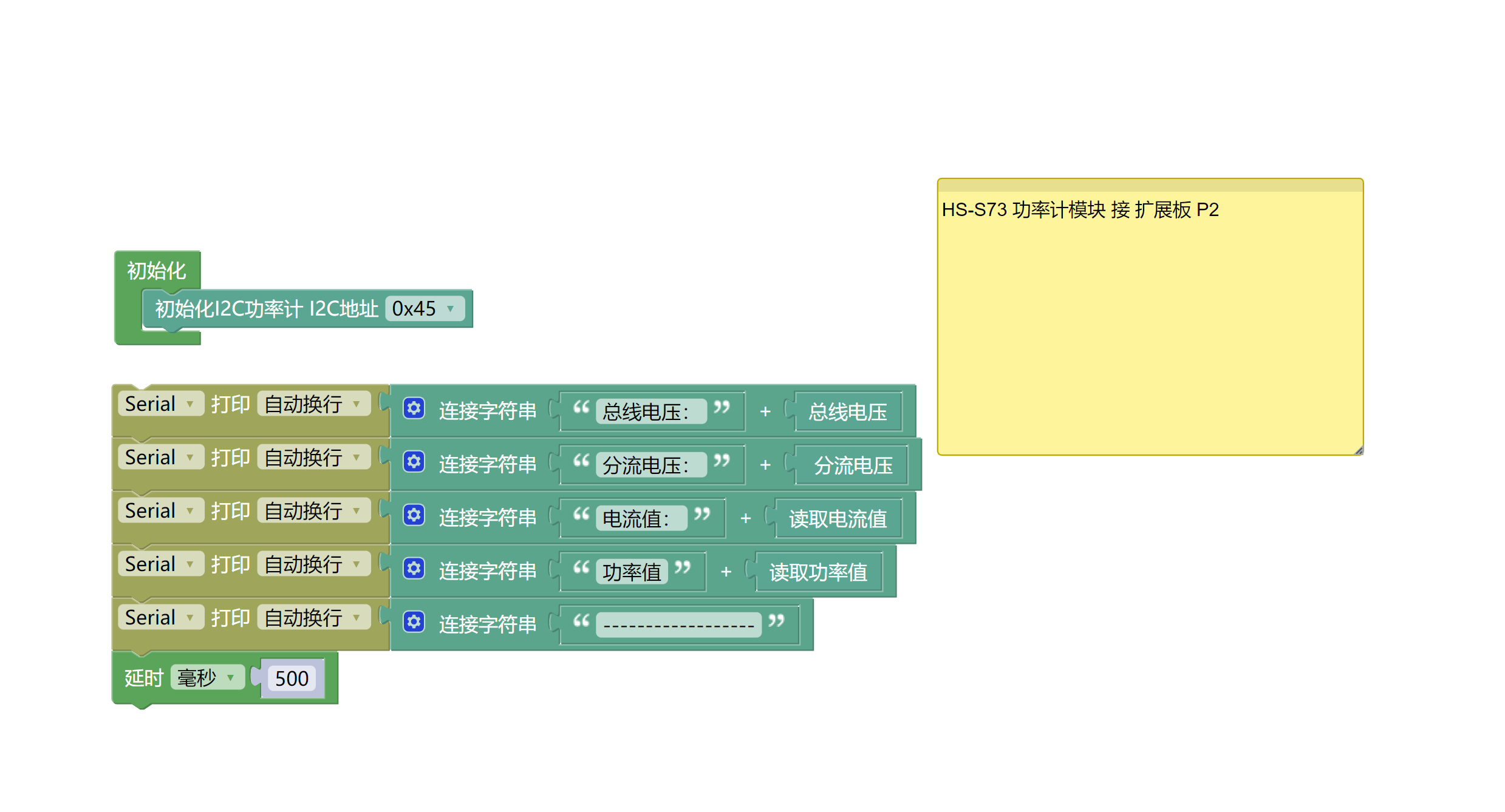
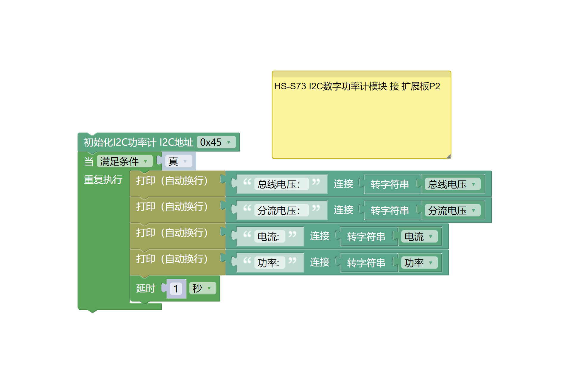
8, Mixly Example Program (Graphic Language)
Example Program (UNO Development Board):Click to download
Example Program (ESP32 Development Board):Click to download
9. Setting up the Test Environment
Arduino UNO Test Environment Setup
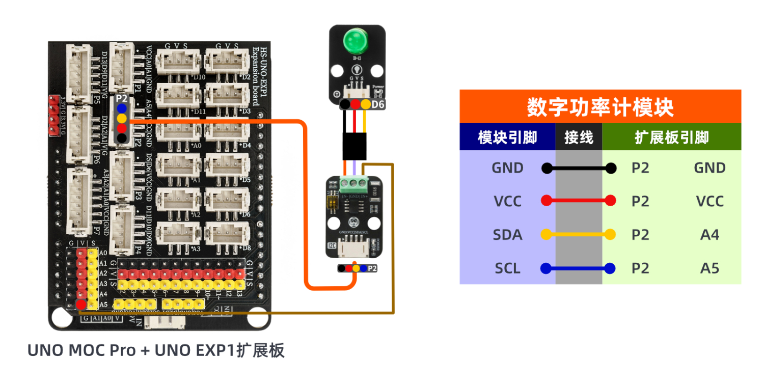
Prepare Components:
UNO-R3 development board *1
UNO-R3 Expansion Board *1
USB TYPE-C DATA CABLE *1
HS-S73-L I2C digital power meter module *1
LED light module *1
PH2.0 4P Double Head Terminal Line *1
Circuit wiring diagram:
ESP32 Python test environment setup
10, video tutorial
Arduino UNO video tutorial: Click to view
ESP32 Python Video Tutorial:
11. Test Conclusion
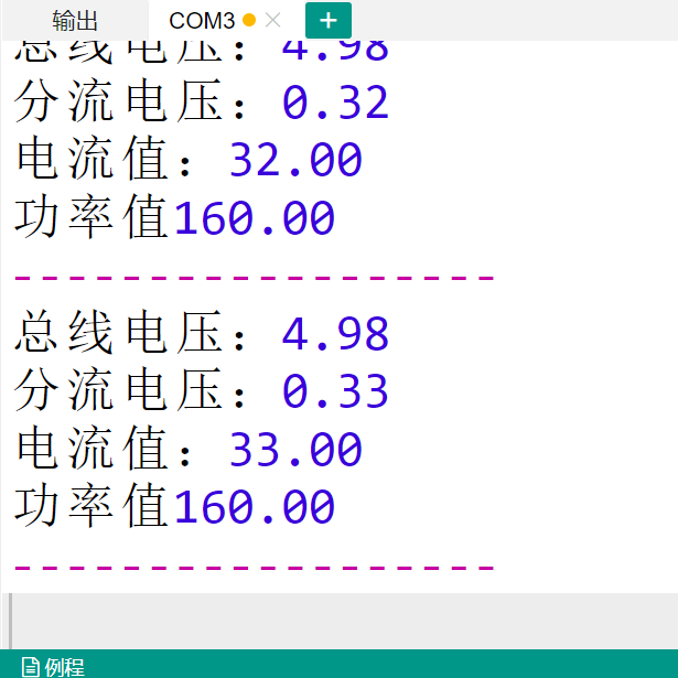
Arduino UNO Test Conclusion:
Found serial port display bus voltage, shunt voltage, current value, power value.