1. Introduction
A seven-segment display, also known as a neon tube, is an electronic device capable of displaying numbers and other information.A glass tube includes an anode made of a metal wire mesh and multiple cathodes, most of the cathode shapes of the digital tube are in the form of numbers.To simplify the driver of the seven-segment display, the module uses a dedicated driver IC 74HC164D.The 74HC164D is an 8-bit serial input parallel output shift register chip.It can convert serial input data into parallel output, making it convenient to directly drive the segments of a digital tube.So it can be realized to control the brightness and extinction of the digital tube with only 2 main control IO ports.
2. Schematic
74HC164D one-digit digital tube - HS-F23-L SchematicClick to view
Module Parameters
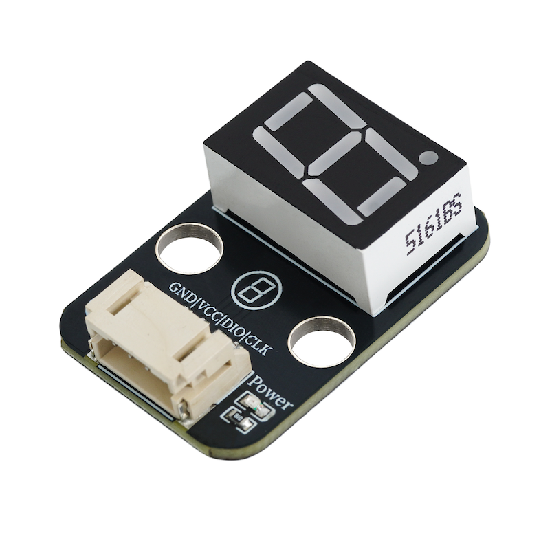
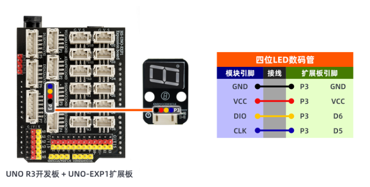
Pin Name | description |
|---|---|
GND | GND (power negative terminal) |
VCC | VCC (power positive terminal) |
DIO | Digital Signal Pin |
CLK | Clock signal pin |
Power Supply Voltage: 3.3V / 5V
Connection method: PH2.0 4P wire
Installation method: Screw fixed / Lego construction
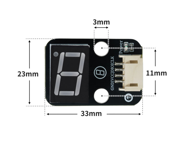
4, Circuit Board Size
5 of Arduino IDE example program
Attention: If prompted with an error message about the library file during program upload, please import the library file first!
Arduino IDE Library Download and Import Tutorial:Click to view
Example program (UNO development board):
char mylist[11]={0xc0,0xf9,0xa4,0xb0,0x99,0x92,0x82,0xf8,0x80,0x90};

void setup(){
  pinMode(6, OUTPUT);
  pinMode(5, OUTPUT);
}

void loop(){
  for (int i = 0; i <= 9; i = i + (1)) {
    shiftOut(6, 5, MSBFIRST, mylist[i]);
    delay(1000);
  }

}
6, ESP32 Python Example (for Mixly IDE/Misashi)
Choose the development board Python ESP32 [ESP32 Generic(4MB)] and upload in code mode
Attention: If prompted with an error message about the library file during program upload, please import the library file first!
Download and import tutorial for Mixly IDE ESP32 library:Click to view
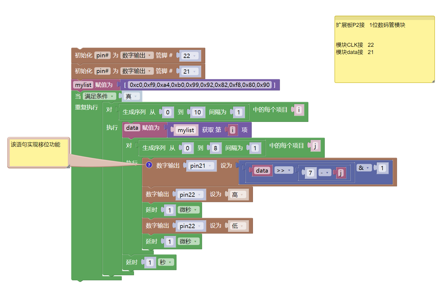
Example program (ESP32-Python):
import machine
import time
pin22 = machine.Pin(22, machine.Pin.OUT)
pin21 = machine.Pin(21, machine.Pin.OUT)
mylist = [0xc0,0xf9,0xa4,0xb0,0x99,0x92,0x82,0xf8,0x80,0x90]
while True:
for i in range(0, 10, 1):
data = mylist[i]
for j in range(0, 8, 1):
# 该语句实现移位功能
pin21.value(((data>>(7 - j))&1))
pin22.value(1)
time.sleep_us(1)
pin22.value(0)
time.sleep_us(1)
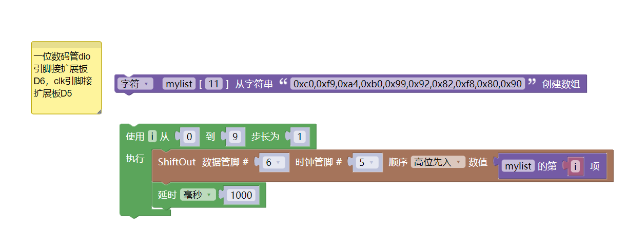
time.sleep(1)7, Mixly example program (graphical language)
Example program (UNO development board):Click to download
Attention: If prompted with an error message about the library file during program upload, please import the library file first!
Download and import tutorial of Mixly IDE Arduino library:Click to view
Example Program (ESP32 Development Board):Click to download
Attention: If prompted with an error message about the library file during program upload, please import the library file first!
Download and import tutorial for Mixly IDE ESP32 library:Click to view
8. Setting up the Test Environment
Arduino UNO Test Environment Setup
Prepare Components:
HELLO STEM UNO R3 PRO DEVELOPMENT BOARD *1
R3P expansion board *1
USB TYPE-C DATA CABLE *1
1-digit digital tube (HS-F23-L) *1
PH2.0 4P dual-head terminal line *1 or PH2.0 4P terminal to Dupont wire *1
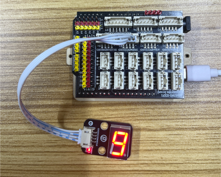
Circuit wiring diagram:
ESP32 Test Environment Setup
Prepare Components:Pending update...
Circuit wiring diagram:Pending update...
9, Video tutorial
Video tutorial:Click to view
10, Test results
Arduino UNO test results:
After the device is connected to the wires, burn the above program to the UNO-R3 PRO development board, then connect the power supply. After that, you can observe the digital tube starting the countdown.