
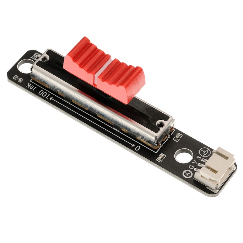
1. Introduction
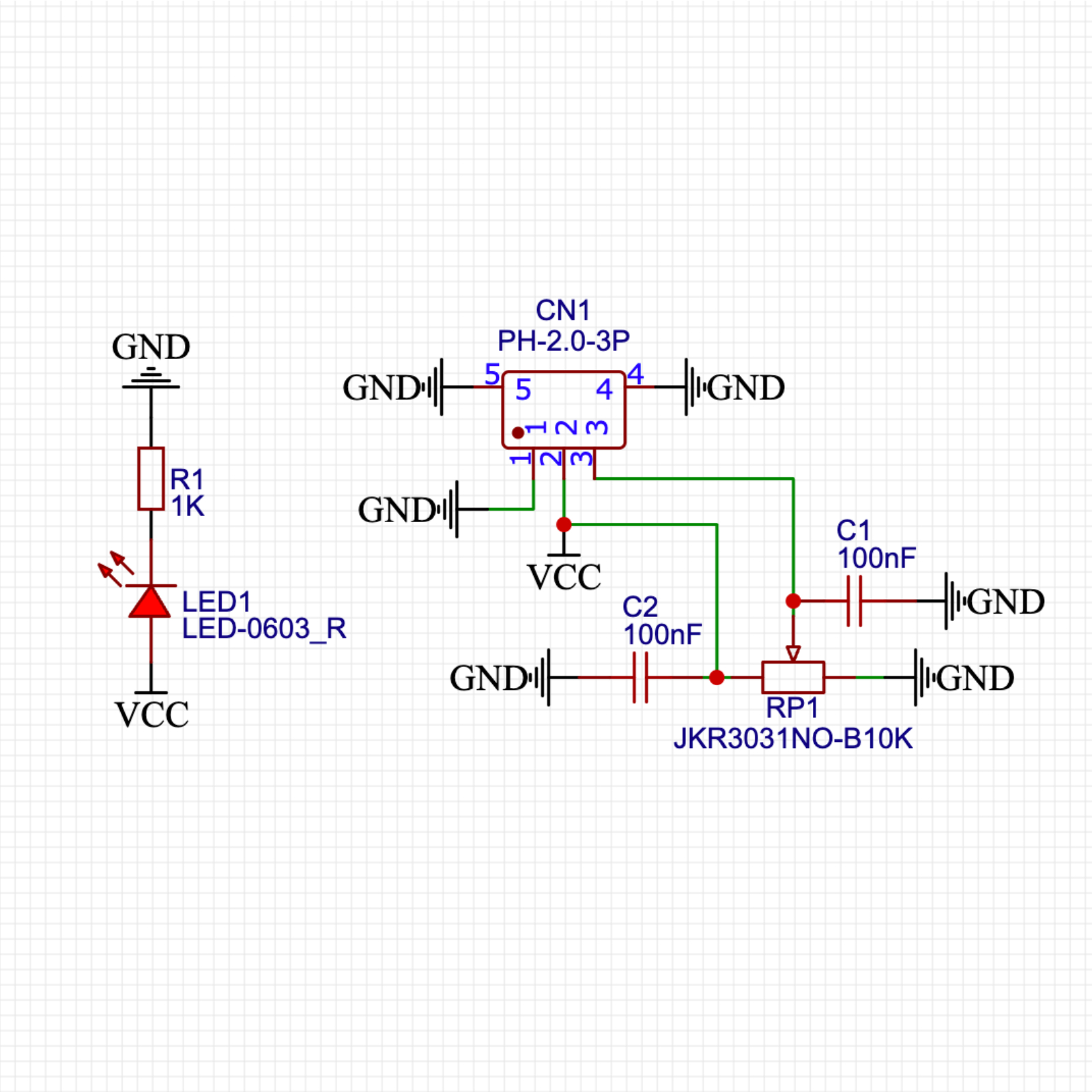
2. Schematic
Module Parameters
Pin Name | description |
|---|---|
G | GND (Negative Power Input) |
V | VCC (Positive Power Input) |
S | Analog Signal Pin |
Power Supply Voltage: 3.3V / 5V
Connection method: PH2.0 terminal wire
Installation Method: Double Screw Fixed
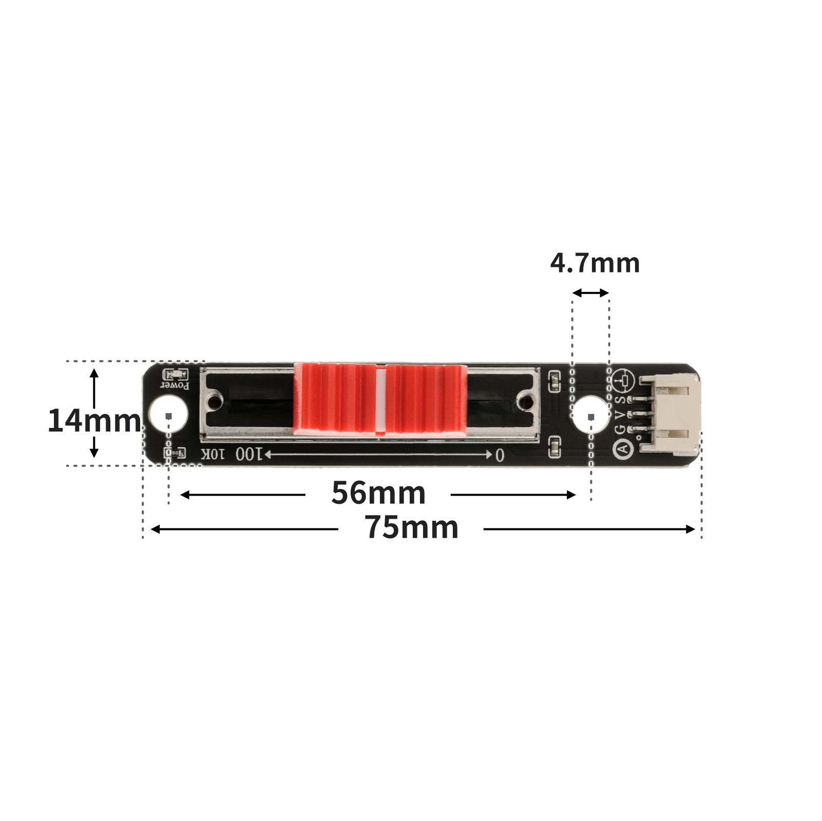
4, Circuit Board Size
5 of Arduino IDE example programClick here to return to the directory
Arduino UNO Graphical Example Program:
volatile int sensorValue;
void setup(){
Serial.begin(9600);
sensorValue = 0;
pinMode(A0, INPUT);
}
void loop(){
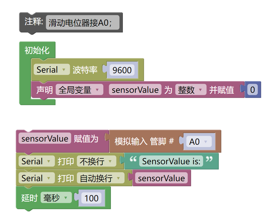
//滑动电位器接A0;
sensorValue = analogRead(A0);
Serial.print("SensorValue is:");
Serial.println(sensorValue);
delay(100);
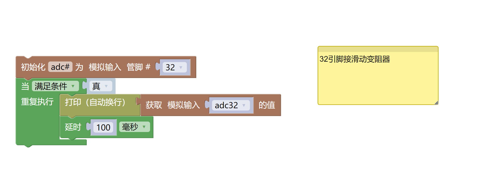
}ESP32 Python Example (for Mixly IDE / Micskit)
(Choose the Python ESP32 [ESP32 Generic(4MB)] to switch to code mode upload):
import machine
import time
adc32 = machine.ADC(machine.Pin(32))
while True:
print(adc32.read_u16())
time.sleep_ms(100)
6, Miciqi Mixly Example Program (Graphical Language)
Arduino UNO Graphical Example Program:Click to download
ESP32 Python Graphical Example Program:Click to download
7, Test Environment Setup
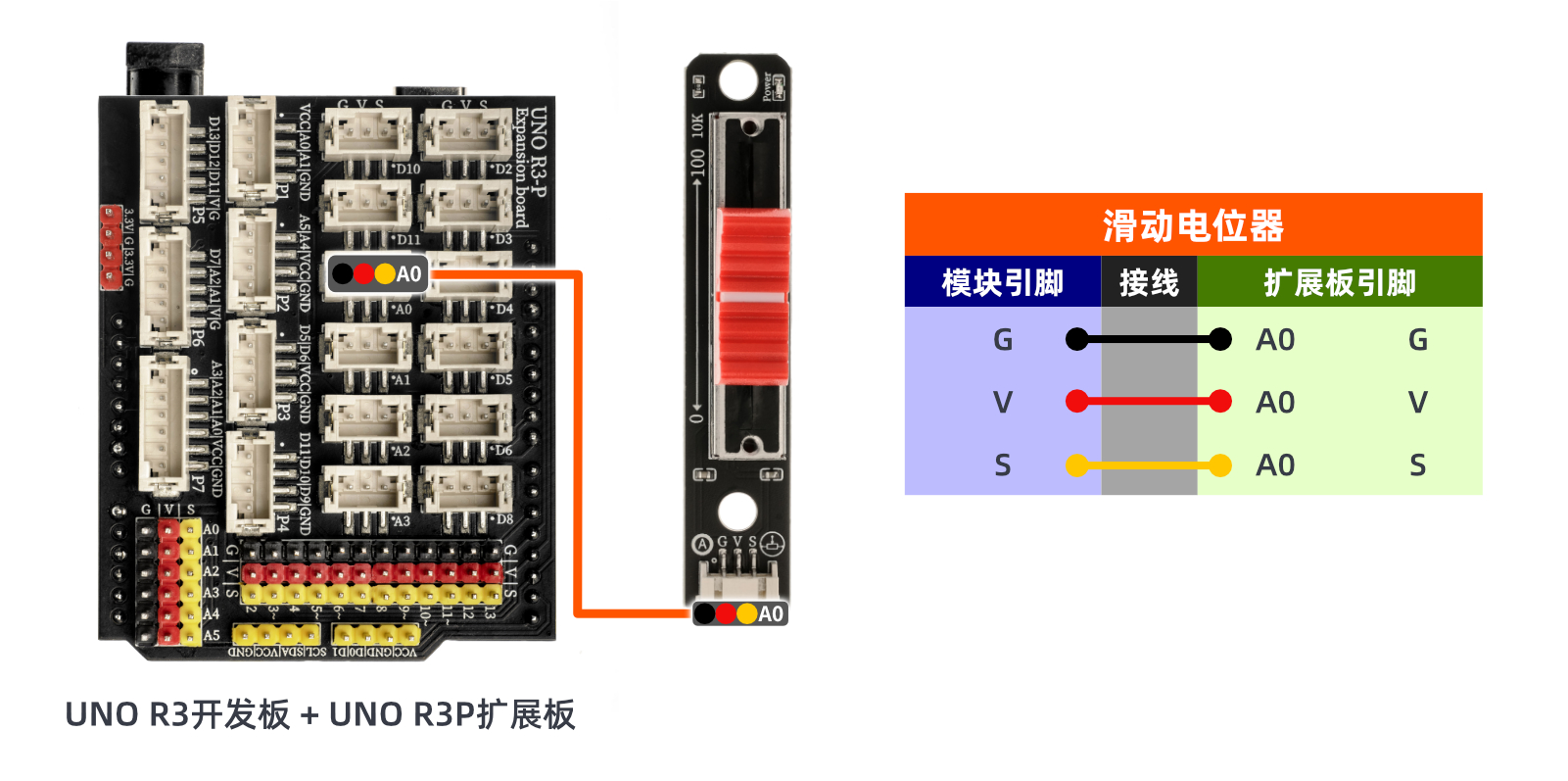
Arduino UNO Test Environment Setup
Prepare Components:
UNO-R3 Development Board *1
UNO-R3 P Expansion Board *1
USB TYPE-C DATA CABLE *1
Rotary encoder module (HS-S25L) *1
PH2.0 3P dual headed terminal line *1
Circuit wiring diagram:
ESP32 Python test environment setup
8. Video tutorial
Arduino UNO video tutorial:Click to view
ESP32 Python Video Tutorial:
9. Test conclusion
Arduino UNO Test Conclusion:
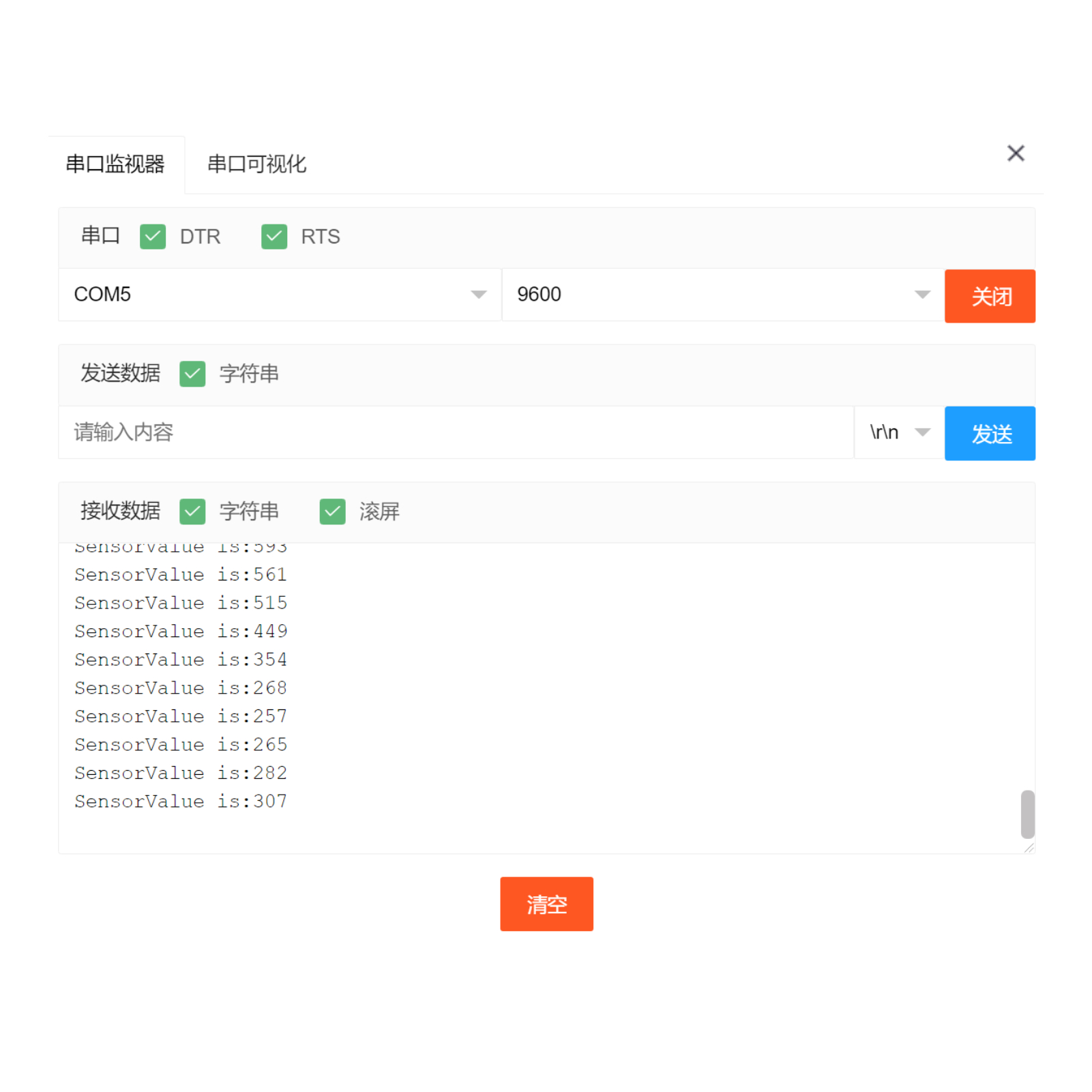
By sliding the wheel of the variable resistor, you can see the simulated value change in the monitoring window.
ESP32 Python test conclusion:By sliding the wheel of the variable resistor, you can see the simulated value change in the monitoring window.