1. Introduction
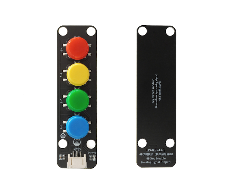
A four-wire simulated independent push-button switch includes 4 four-leg push-buttons, which are protected by metal strips to protect the force condition; in the four-wire push-button switch, when a button is pressed, the circuit is conductive; when the pressure is released, the circuit is open.The force of pressure, is the action of using our hands to press buttons, turn on and off.Four push-button switches share a single analog output. The analog value output varies when different buttons are pressed, allowing for the determination of which button is pressed. The four analog switch modules contain 4 instantaneous press buttons, and the interface of this module simulates analog signals. The working principle of the simulated switch is to switch the output status of the signal according to the analog value of the input signal.The simulation switch usually has multiple input channels and one output channel, and it can select the channel to be connected to the output by controlling the input signal.We can control four buttons using an Arduino's analog port, which can greatly reduce the need for using IO interfaces.For Arduino beginners, creation is more convenient.
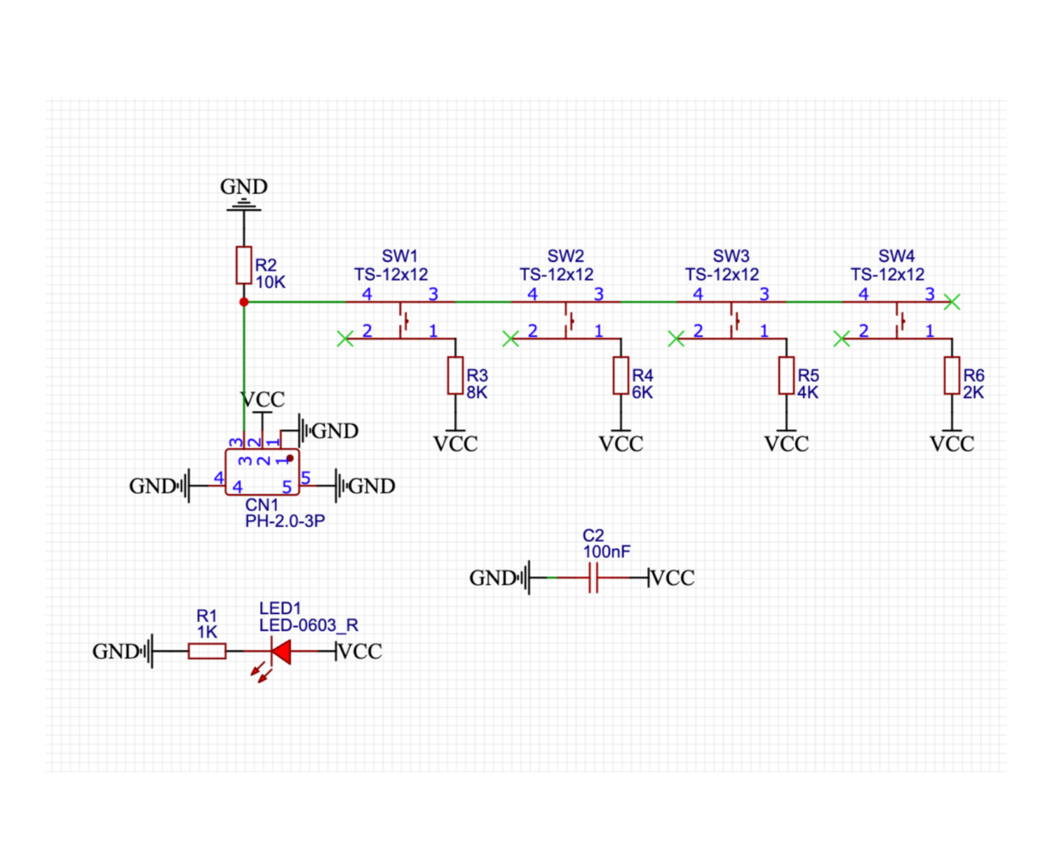
2. Schematic
Module Parameters
Pin Name | description |
|---|---|
G | GND (Negative Power Input) |
V | VCC (Positive Power Input) |
S | Analog Signal Pin |
Power Supply Voltage: 3.3V / 5V
Connection method: PH2.0 terminal wire
Installation method: Modular fixed
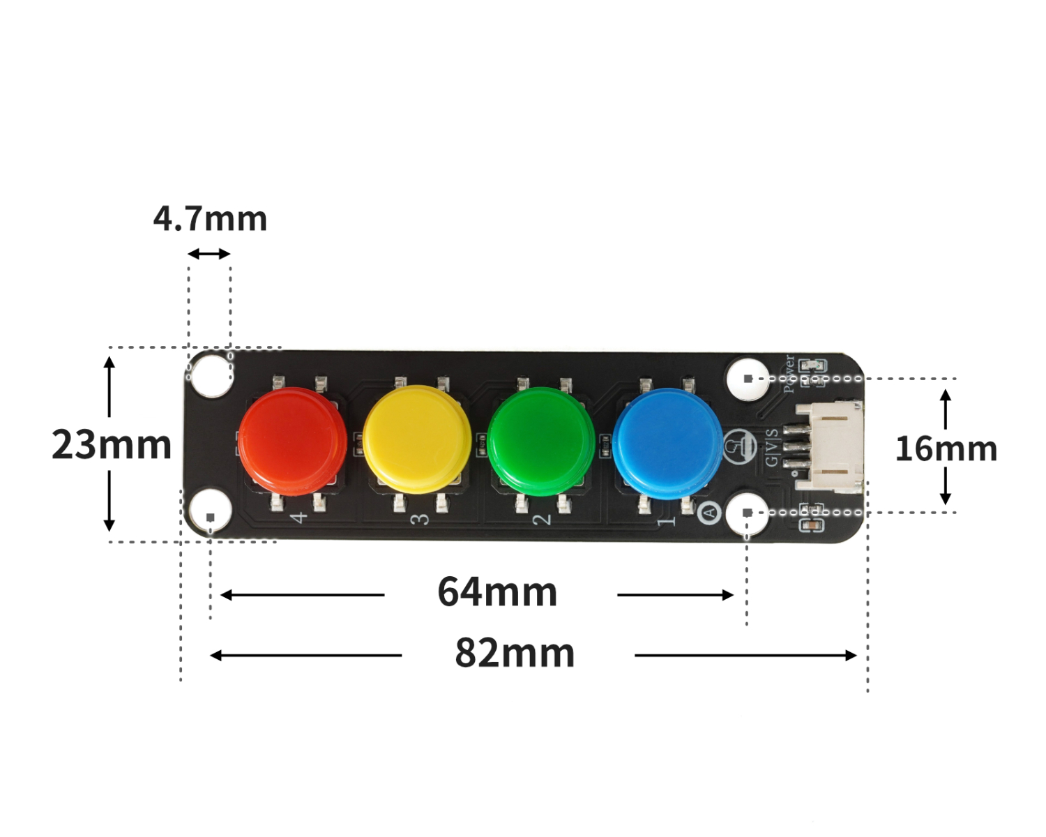
4, Circuit Board Size
5 of Arduino IDE example program
Example program (UNO development board):Click to download
volatile int led;
volatile int light;
volatile int vaule;
void setup(){
Serial.begin(9600);
led = 6;
light = 0;
vaule = 0;
//led接D6,四位模拟按键模块接A0
pinMode(A0, INPUT);
}
void loop(){
vaule = analogRead(A0);
Serial.println(vaule);
analogWrite(led, light);
if (vaule < 565 && vaule > 555) {
//关灯
light = 0;
} else if (vaule < 640 && vaule > 630) {
//微亮
light = 15;
} else if (vaule < 720 && vaule > 710) {
//亮
light = 100;
} else if (vaule < 860 && vaule > 850) {
//非常亮
light = 255;
}
}Example Program (ESP32 Development Board — Based on Python language, cannot be uploaded using Arduino IDE):
6, Miciqi Mixly Example Program (Graphical Language)
Example program:Click to download

Example Program (ESP32 Development Board): Click to download
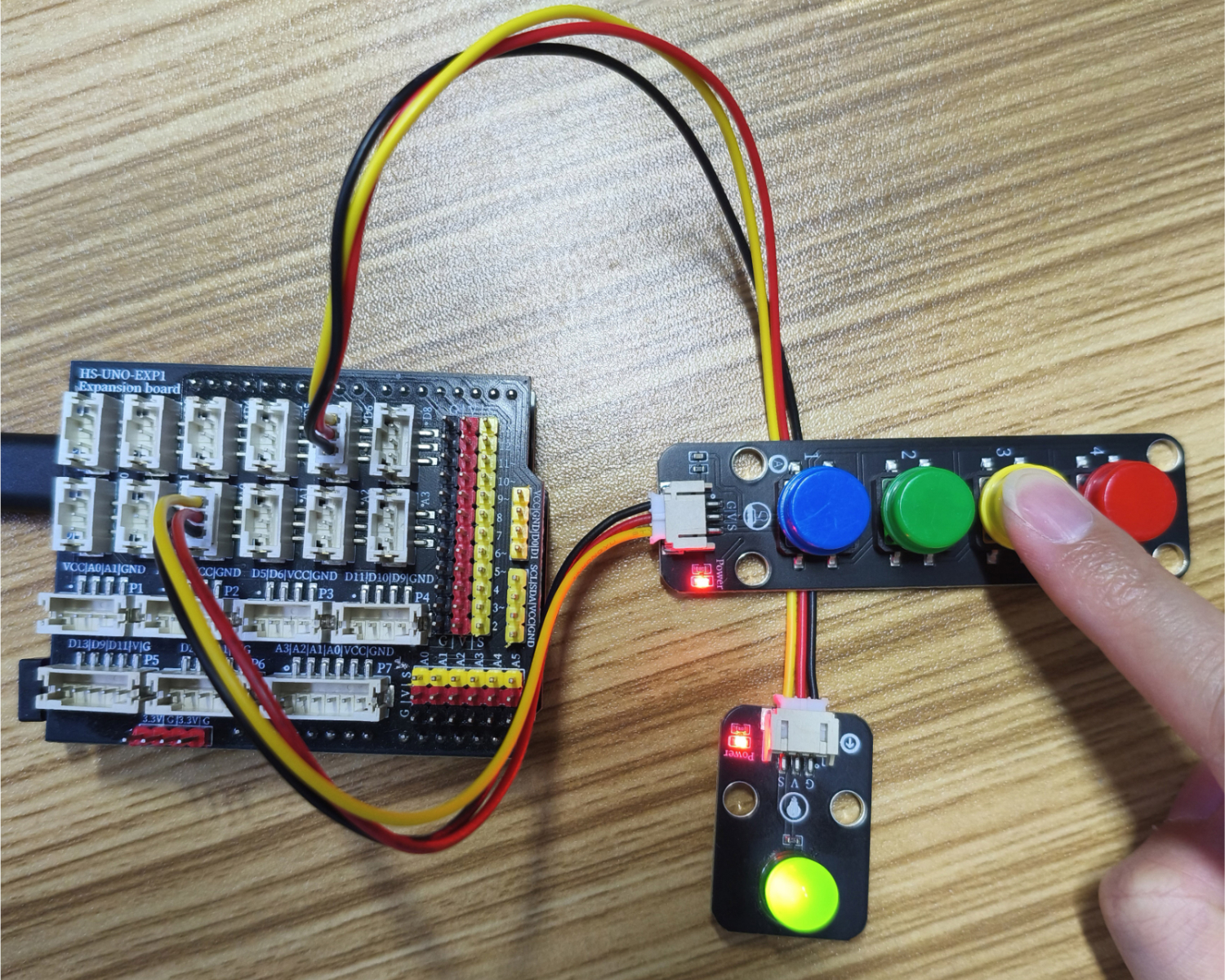
7, Test Environment Setup
Setting up the Arduino Environment
Prepare Components:
HELLO STEM UNO R3 DEVELOPMENT BOARD *1
HELLO STEM UNO R3 P EXPANSION BOARD *1
USB TYPE-C DATA CABLE *1
LED module (HS-F08P) *1
4-Key Analog Pushbutton Module (HS-KEY4A-L) *1
PH2.0 3P terminal to DuPont wire *2 or PH2.0 3P dual-head terminal wire *2
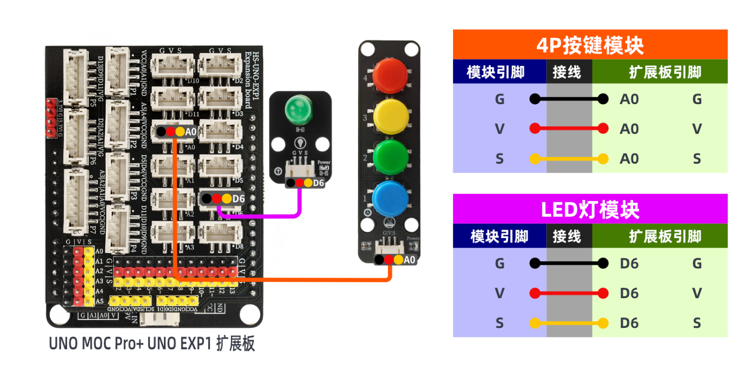
Circuit wiring diagram:
Set up Micropython environment
Prepare Components:
Circuit wiring diagram:
8. Video tutorial
Video tutorial:Click to view
9. Test conclusion