
1. Introduction
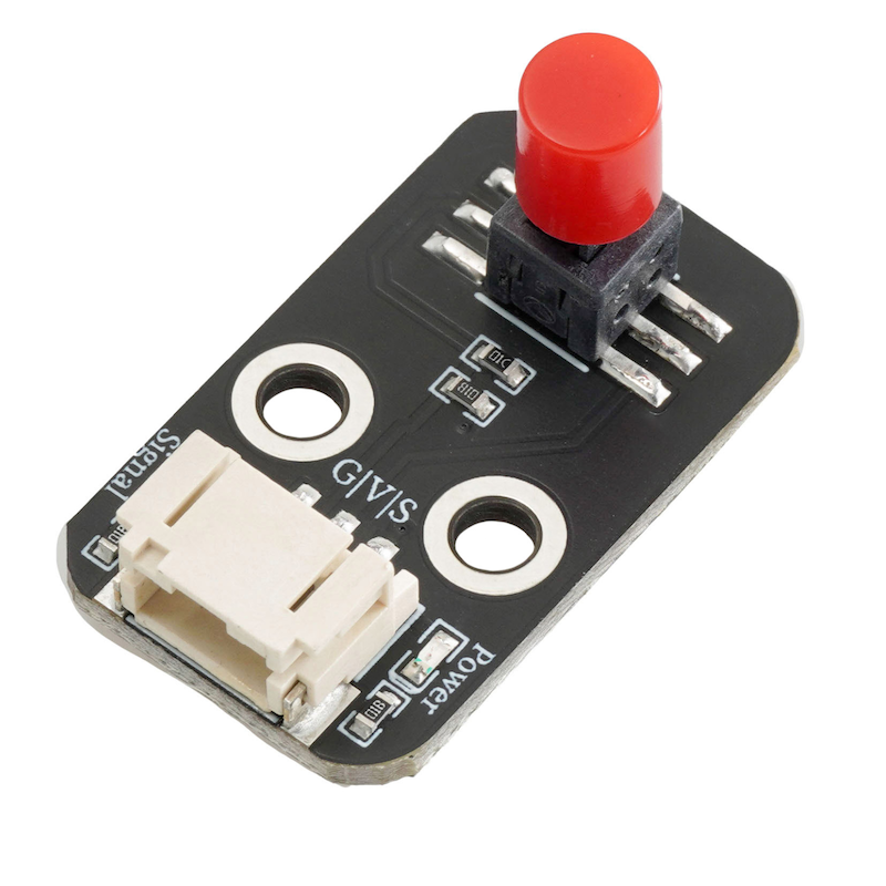
The lockout switch module, after pressing the switch, keeps the switch state locked in place by means of a mechanical lock or electronic circuit, even if the external force disappears, the switch can still remain in the closed or open state until a specific operation is applied to change its state.
2. Schematic
Locking switch module-HS-S66P schematicClick to view
Module Parameters
Pin Name | description |
|---|---|
G | GND (Negative Power Input) |
V | VCC (Positive Power Input) |
S | Digital Signal Pin |
Power Supply Voltage: 3.3V / 5V
Connection method: PH2.0 terminal wire
Installation method: Screw fixed
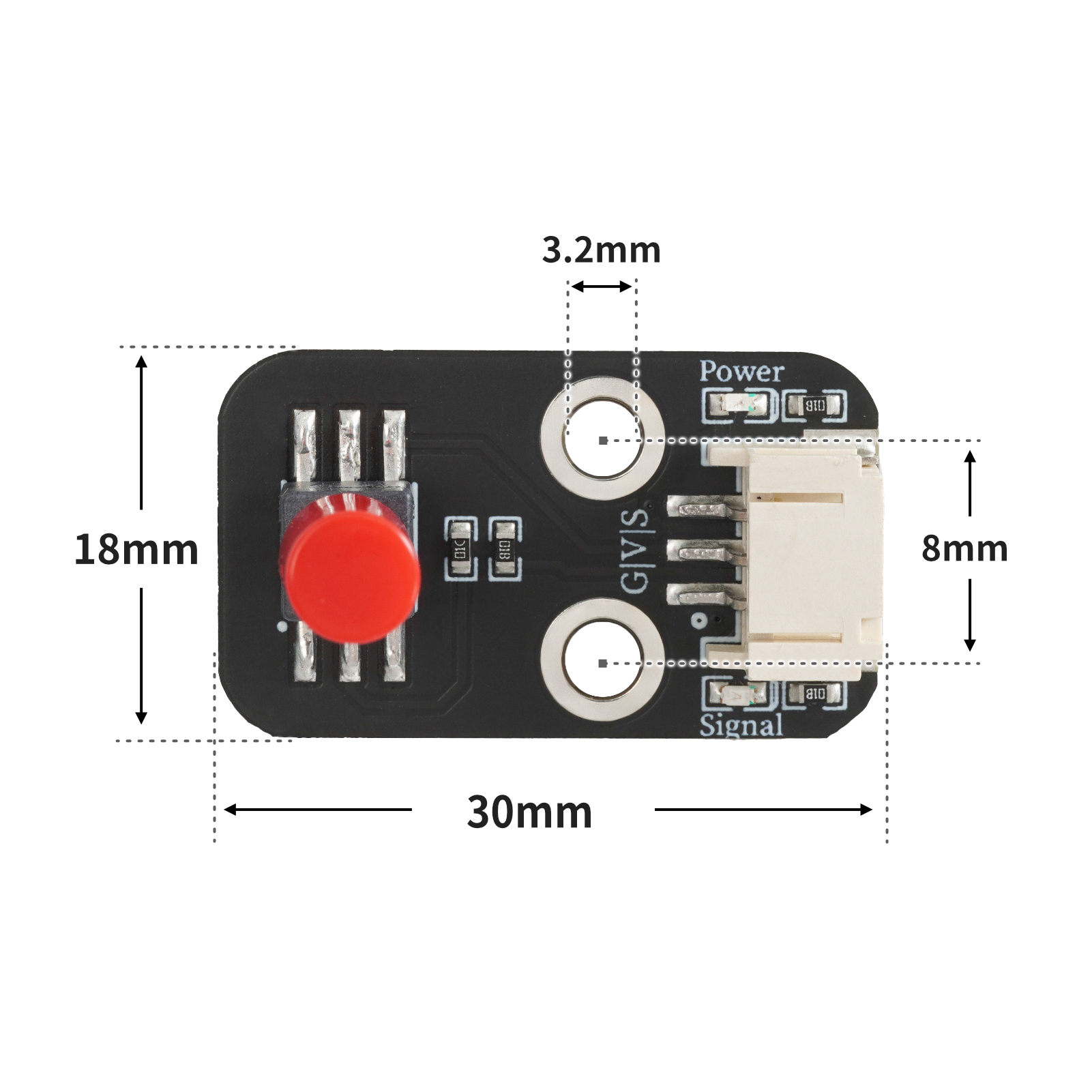
4, Circuit Board Size
5 of Arduino IDE example program
Attention: If prompted with an error message about the library file during program upload, please import the library file first!
Arduino IDE Library Download and Import Tutorial:Click to view
Example program (UNO development board):
void setup(){
Serial.begin(9600);
pinMode(4, INPUT);
pinMode(6, OUTPUT);
}
void loop(){
if (digitalRead(4) == HIGH) {
digitalWrite(6,HIGH);
} else {
digitalWrite(6,LOW);
}
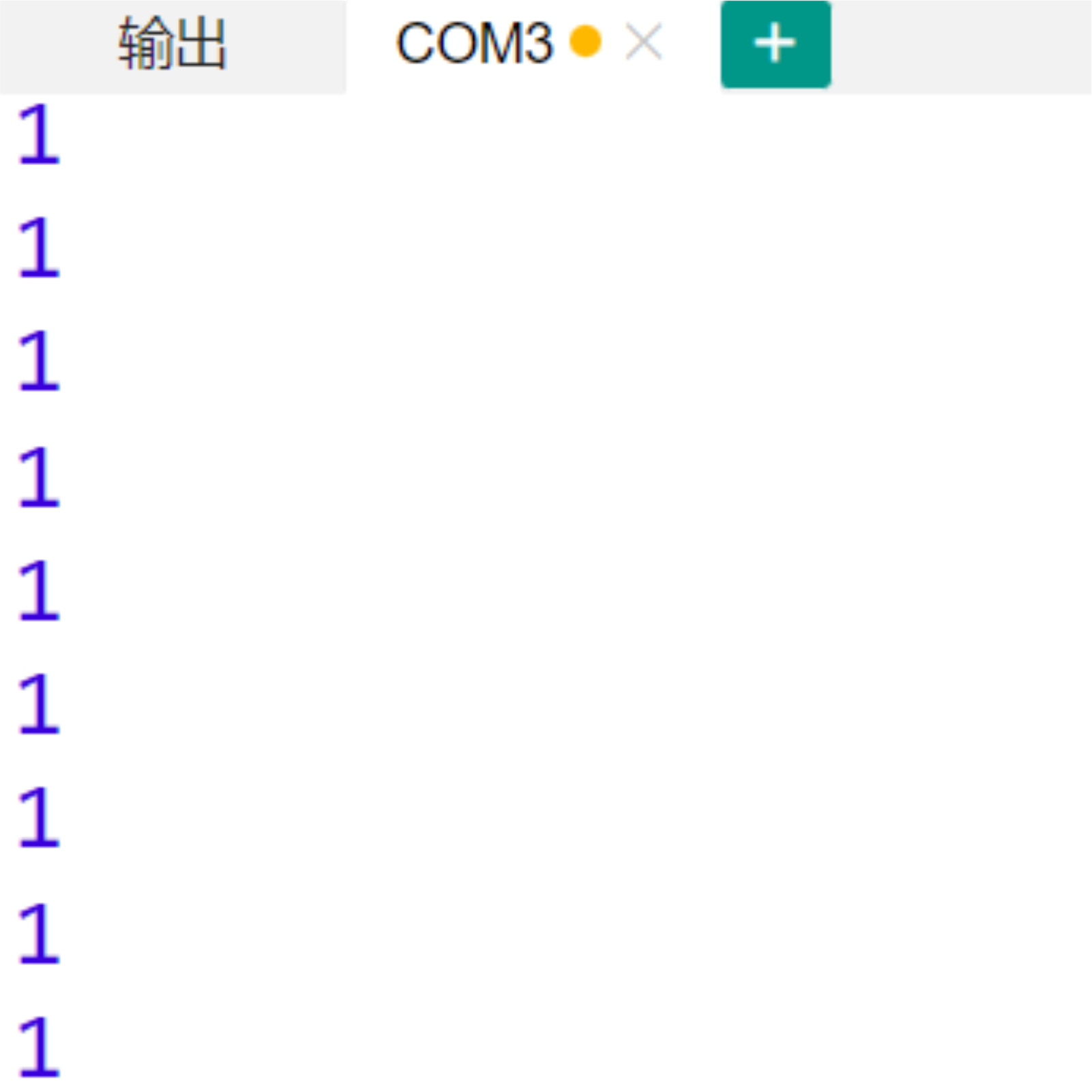
Serial.println(digitalRead(4));
}6, ESP32 Python Example (for Mixly IDE/Misashi)
Choose the development board Python ESP32 [ESP32 Generic(4MB)] and upload in code mode
Attention: If prompted with an error message about the library file during program upload, please import the library file first!
Download and import tutorial for Mixly IDE ESP32 library:Click to view
Example program (ESP32-Python):
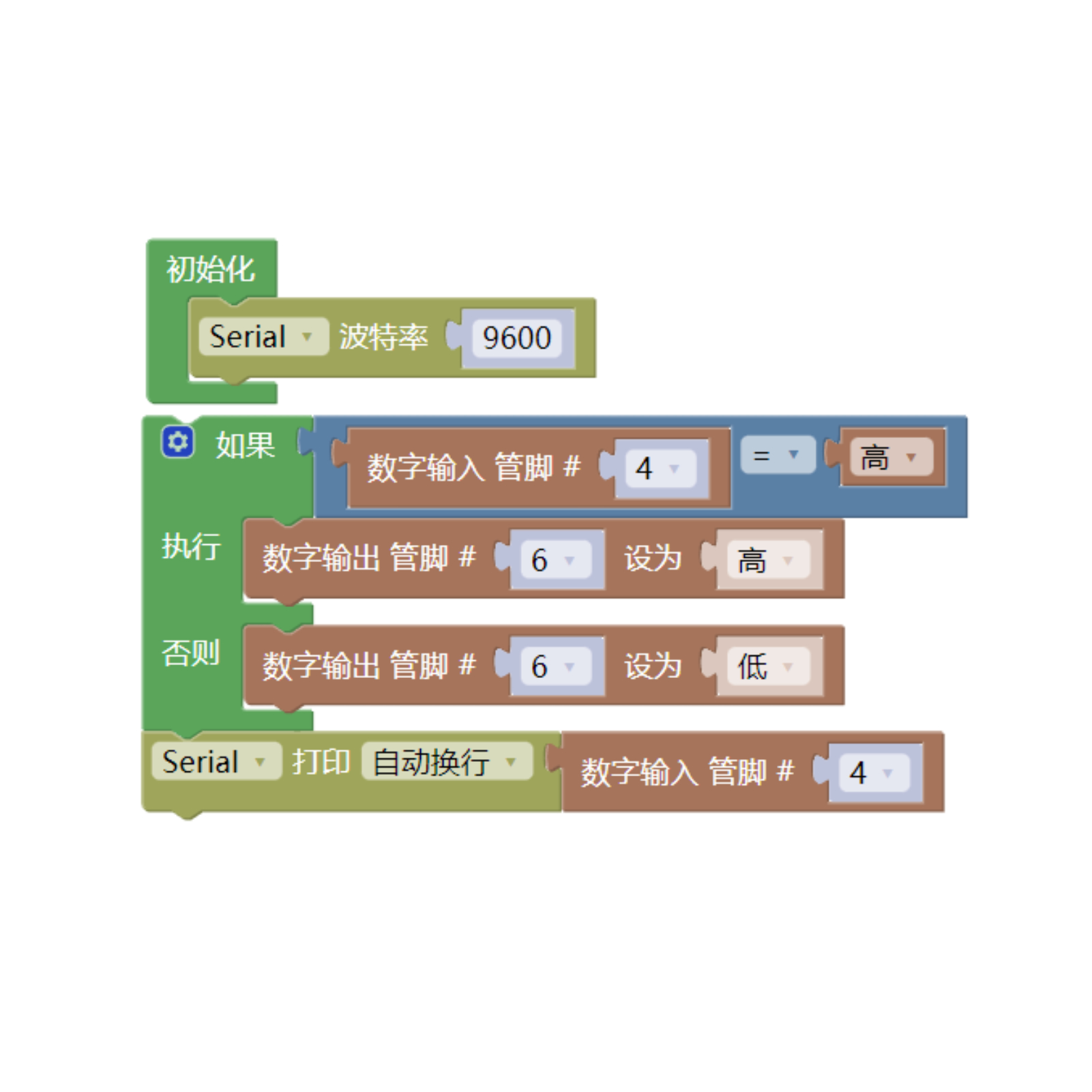
待更新...7, Mixly example program (graphical language)
Example program (UNO development board):Click to download
Attention: If prompted with an error message about the library file during program upload, please import the library file first!
Download and import tutorial of Mixly IDE Arduino library:Click to view
Example Program (ESP32 Development Board):Click to download
Attention: If prompted with an error message about the library file during program upload, please import the library file first!
Download and import tutorial for Mixly IDE ESP32 library:Click to view
Image pending update...
8. Setting up the Test Environment
Arduino UNO Test Environment Setup
Prepare Components:
HELLO STEM UNO R3 DEVELOPMENT BOARD *1
HELLO STEM UNO R3 P EXPANSION BOARD *1
USB TYPE-C DATA CABLE *1
LED module (HS-F08P) *1
Locking pushbutton module (HS-66P) *1
PH2.0 3P terminal to DuPont wire *2 or PH2.0 3P dual-head terminal wire *2
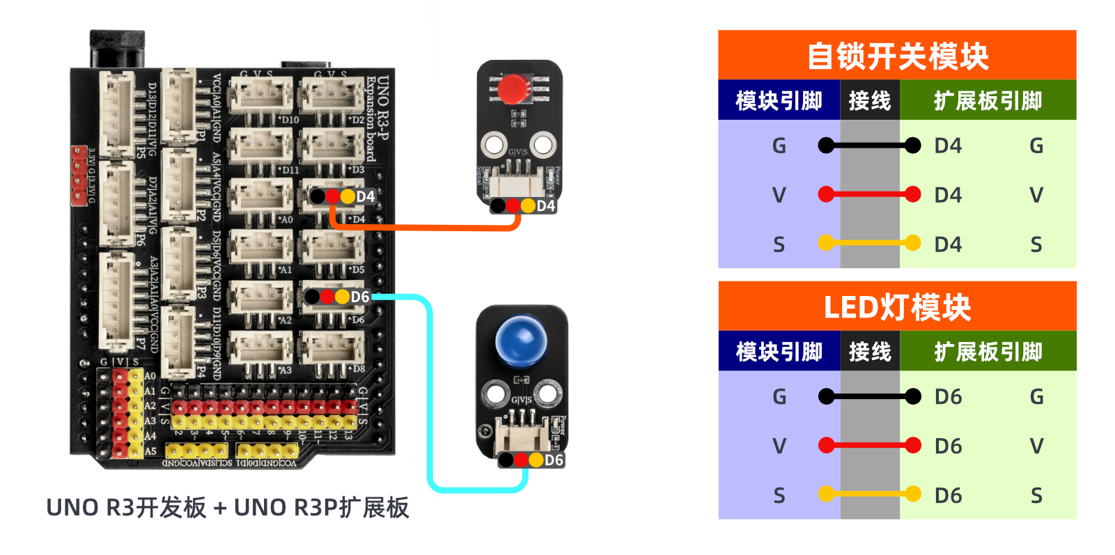
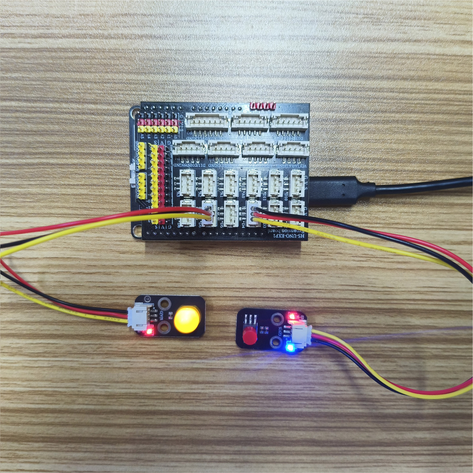
Circuit wiring diagram:
ESP32 Test Environment Setup
Prepare Components:Pending update...
Circuit wiring diagram:Pending update...
9, Video tutorial
Video tutorial:Click to view
10, Test results
Arduino UNO test results:
After the device is connected and the program mentioned above is burned to the UNO-R3 PRO development board, power is applied. Pressing the same button, the LED will remain dark or bright.
ESP32 Test Results:
Pending update...