
1. Download and install Mixly (Mixly) software
Mixly software:mixly
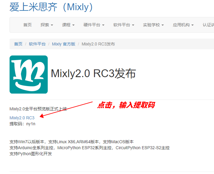
Open the official website of Mixly software:Fall in love with Mixly (Mixly)
Click Mixly2.0RC3 version, then click Mixly2.0 RC file download from the cloud disk
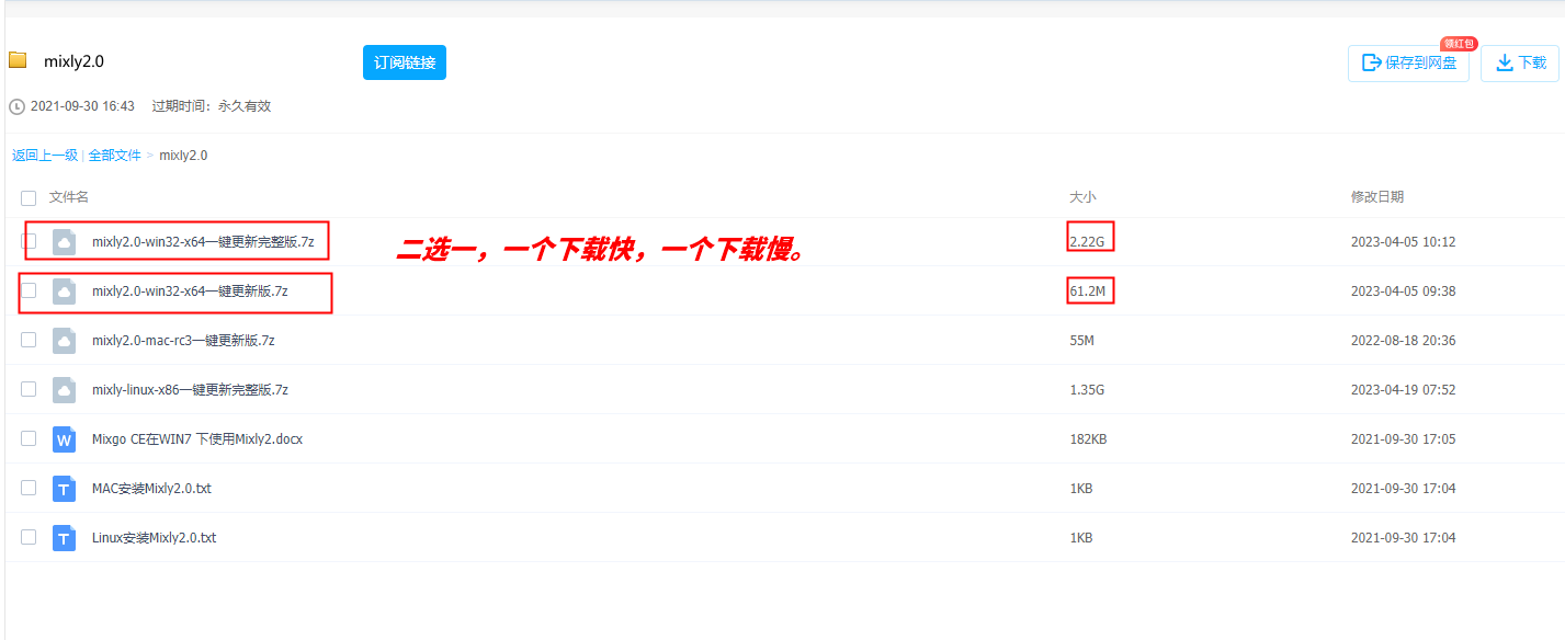
There are four system version software options available, here we take the WIN10-x64 version as an example, most computers are running on the WIN10 system, click to download the software version you need
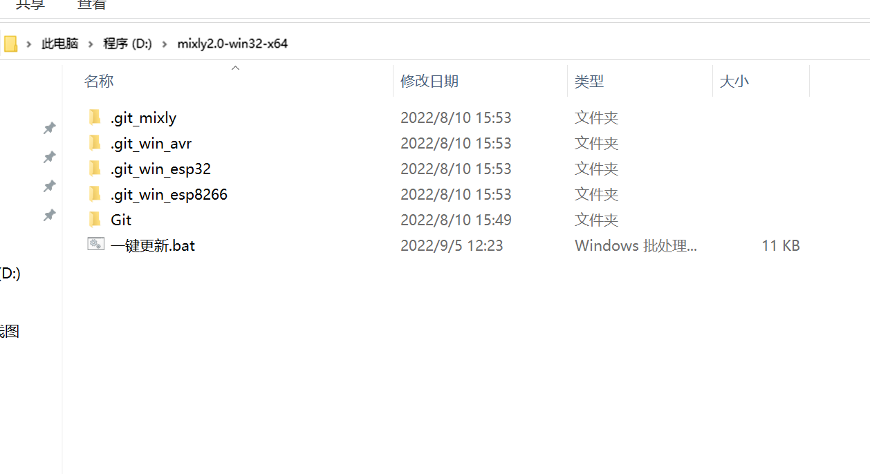
2. Software Installation and Update
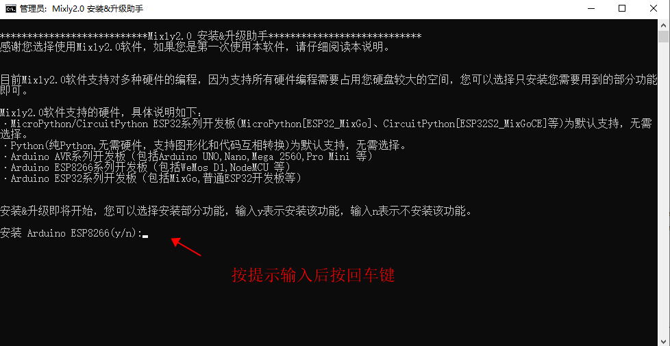
Click the one-click update under the software directory
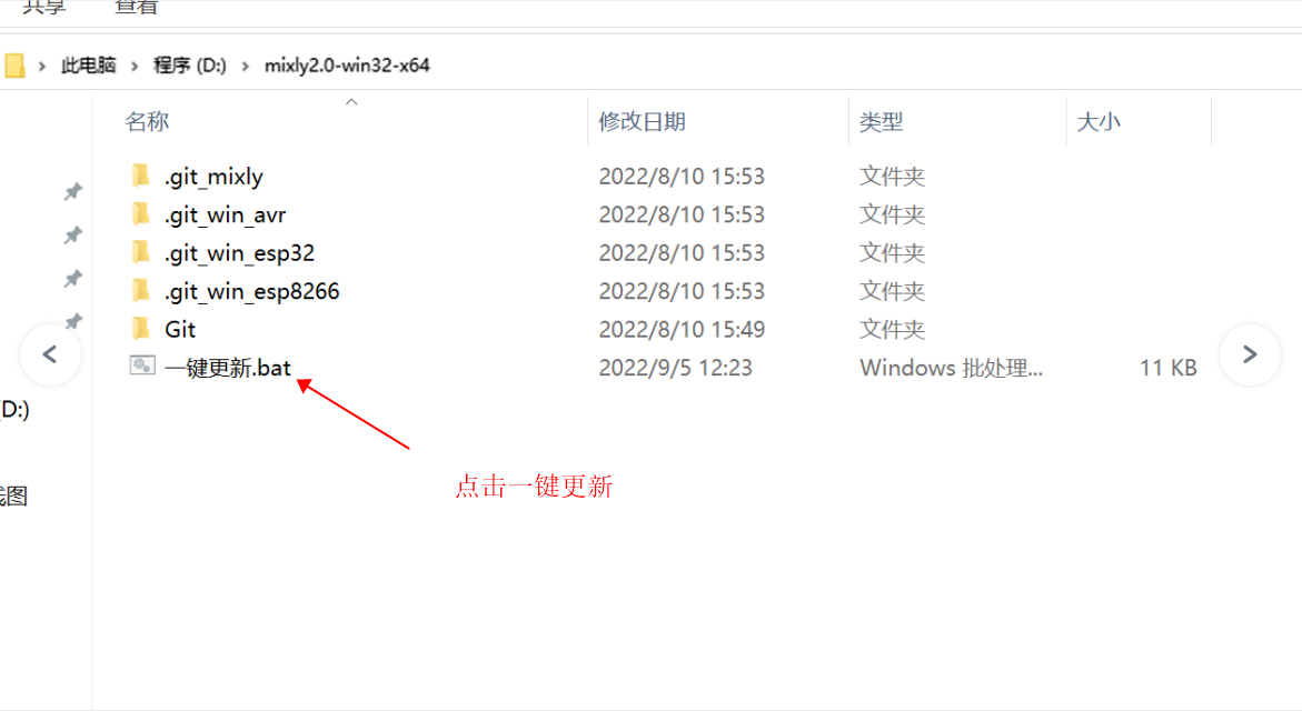
Because our board is an ESP32 series development board, enter 'y' as prompted and press Enter (return key) to install automatically, and press any key on the keyboard to exit after installation is complete
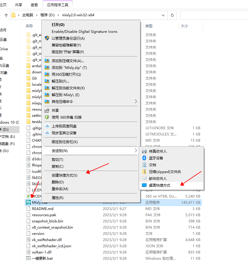
Right-click on Mixly.exe and send it to the desktop for future use.
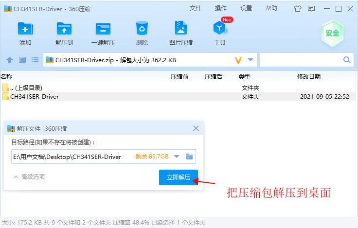
3. Install the development board's USB CH340 serial port driverClick to download
After downloading, extract the compressed package
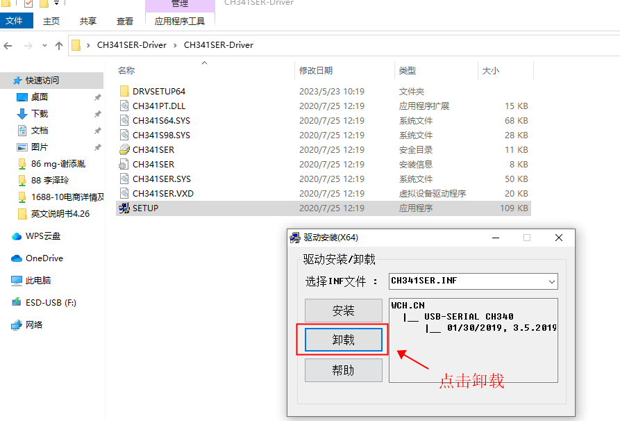
Open the folder and select SETUP by double-clicking
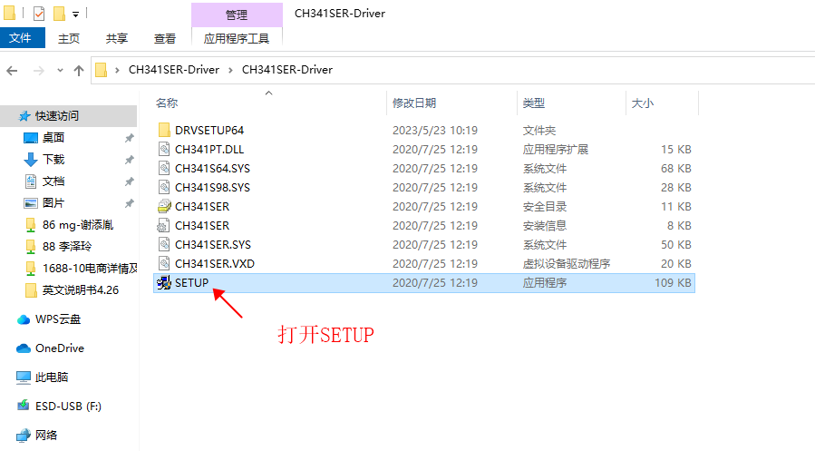
Click to uninstall the previous driver
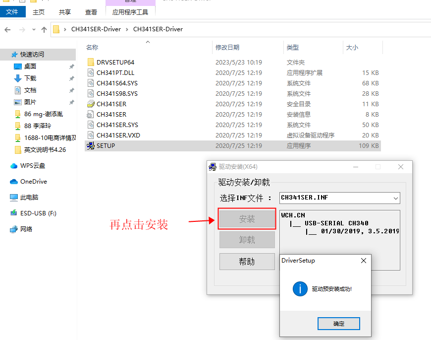
Then click to install the driver
Connect the program card to the computer and then open Device Manager to see if the port is available, indicating that the installation is complete. If it is not displayed, you need to restart the computer or reinstall it
4. Introduction to Micsense software
Mixly is a free open-source graphical programming software based on Google's graphical programming framework.It is a free and open-source graphical programming tool for creative electronics development; it is a complete ecosystem for creative electronics education; it is a stage for makers to realize their dreams.
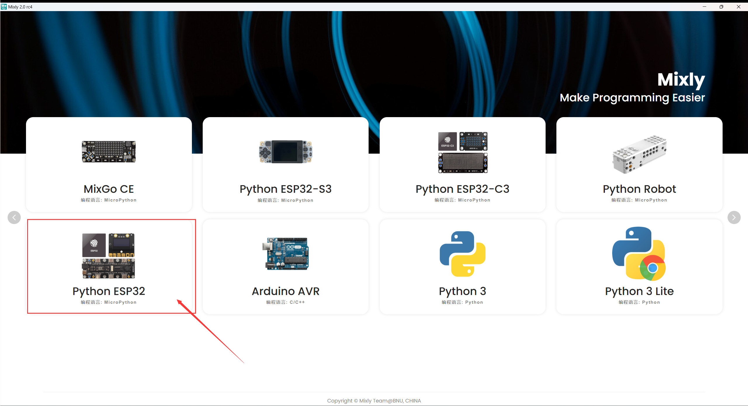
The software is installed, we click on the mixly icon on the computer desktop to open the software, and select Python ESP32

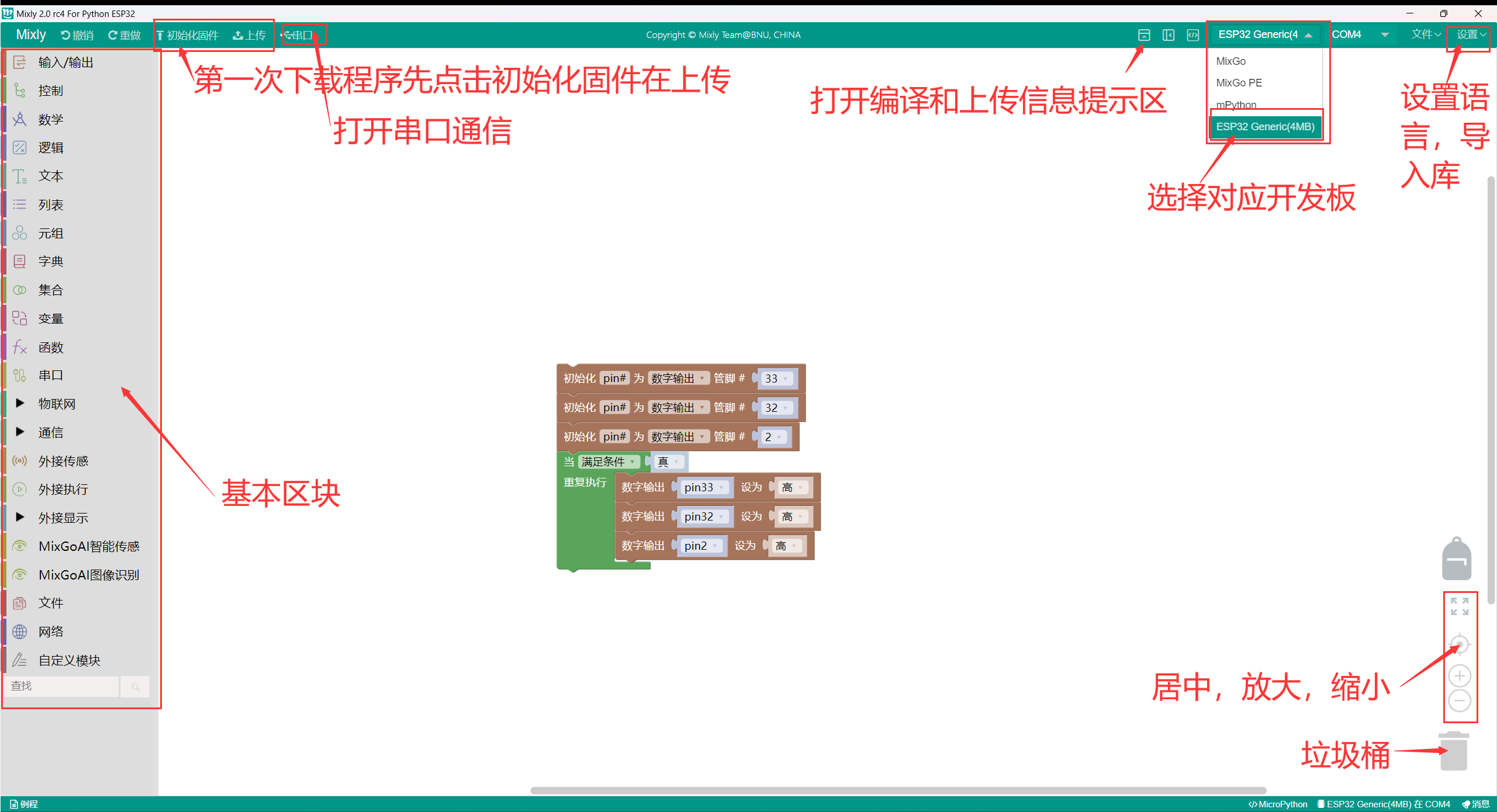
Before uploading the code program to an ESP32 development board or compatible board, you must first understand the functions of each area and interface that appear in the Misaki software toolbar.
Interface layout
The interface is divided into four major functional area blocks in total.
1. Basic functional block area
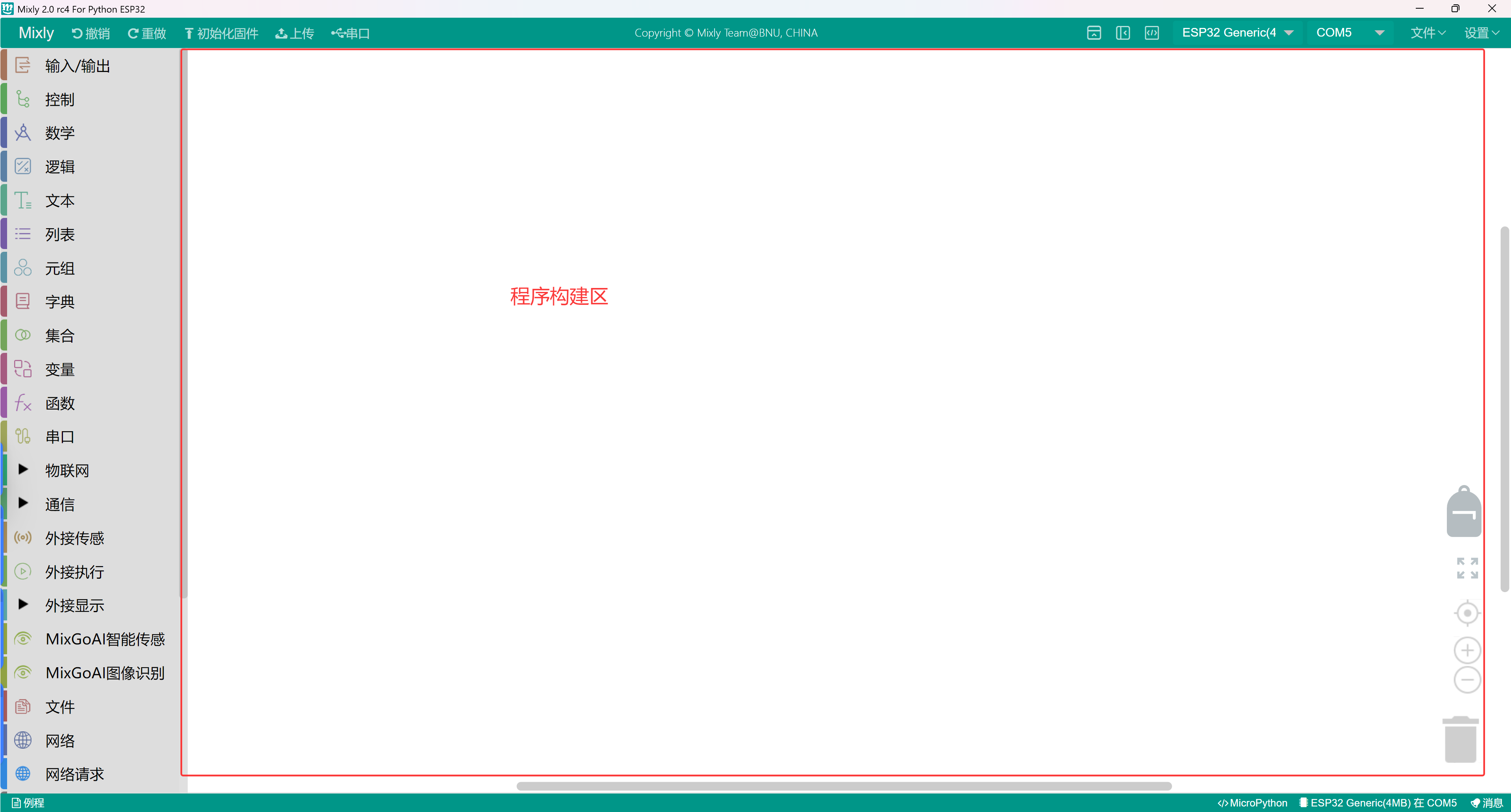
2. Program construction area
3. Code area
4. Information prompt area
Basic Function Block Area
Input/Output: IO-related Function Blocks
Control: Program Flow Control-related Function Blocks
Math: Mathematical Operation-related Function Blocks
Text: Functions related to string operations
Array: Functions related to arrays
Logic: Functions related to logical relationships
Serial Port: Functions related to serial communication
Communication: Ethernet, infrared remote control and other communication function blocks
Storage: Data storage related function blocks (Advanced view)
Sensors: General sensor related function blocks
Actuator: General actuator related function blocks
Display: Display related function blocks
Ethernet: Ethernet communication function block (advanced view)
Variables: Variable operation related function blocks
Function: Function-related feature block
Custom Module: Custom code feature block (Advanced view)
Program Building Area
The area is for program function concatenation.Drag the function block from the left block area into the program construction area for assembly.The bottom right corner of the area has a trash can, where you can drag in unused code to delete it, or directly drag unused code to the leftmost side (module selection area), which can also delete code.
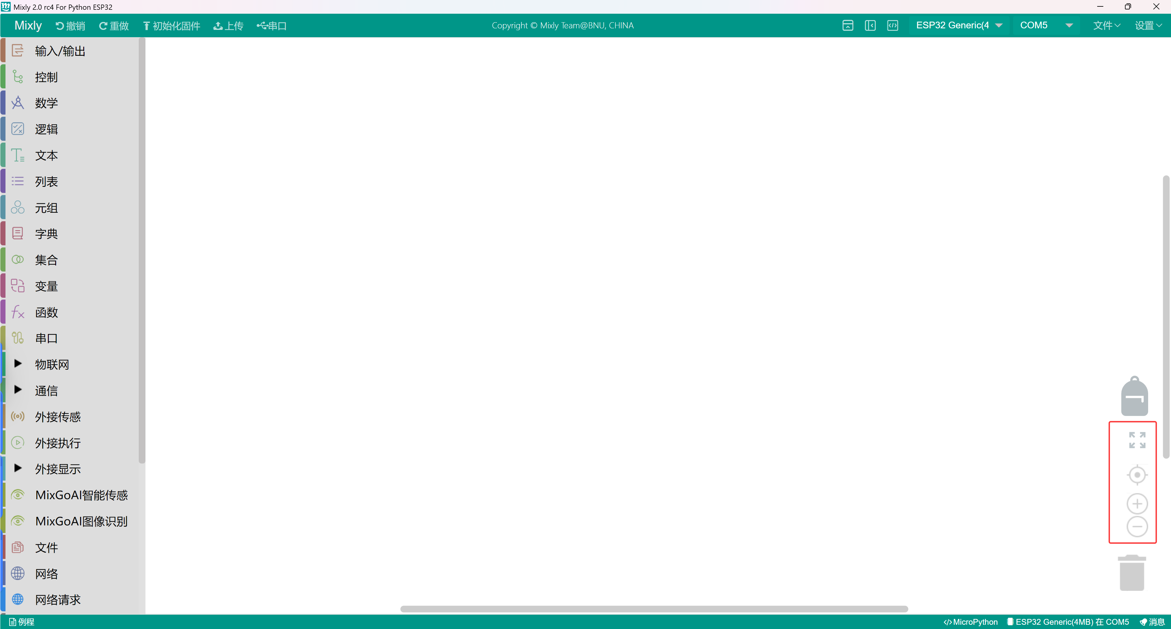
View Zoom
There are two shapes above the trash can, one is ⊕ and the other is Θ. The shape can be zoomed in or out to adjust the program building area module.
The size. There is a button above ⊕, the function of which is to restore the module to the standard size and center it.
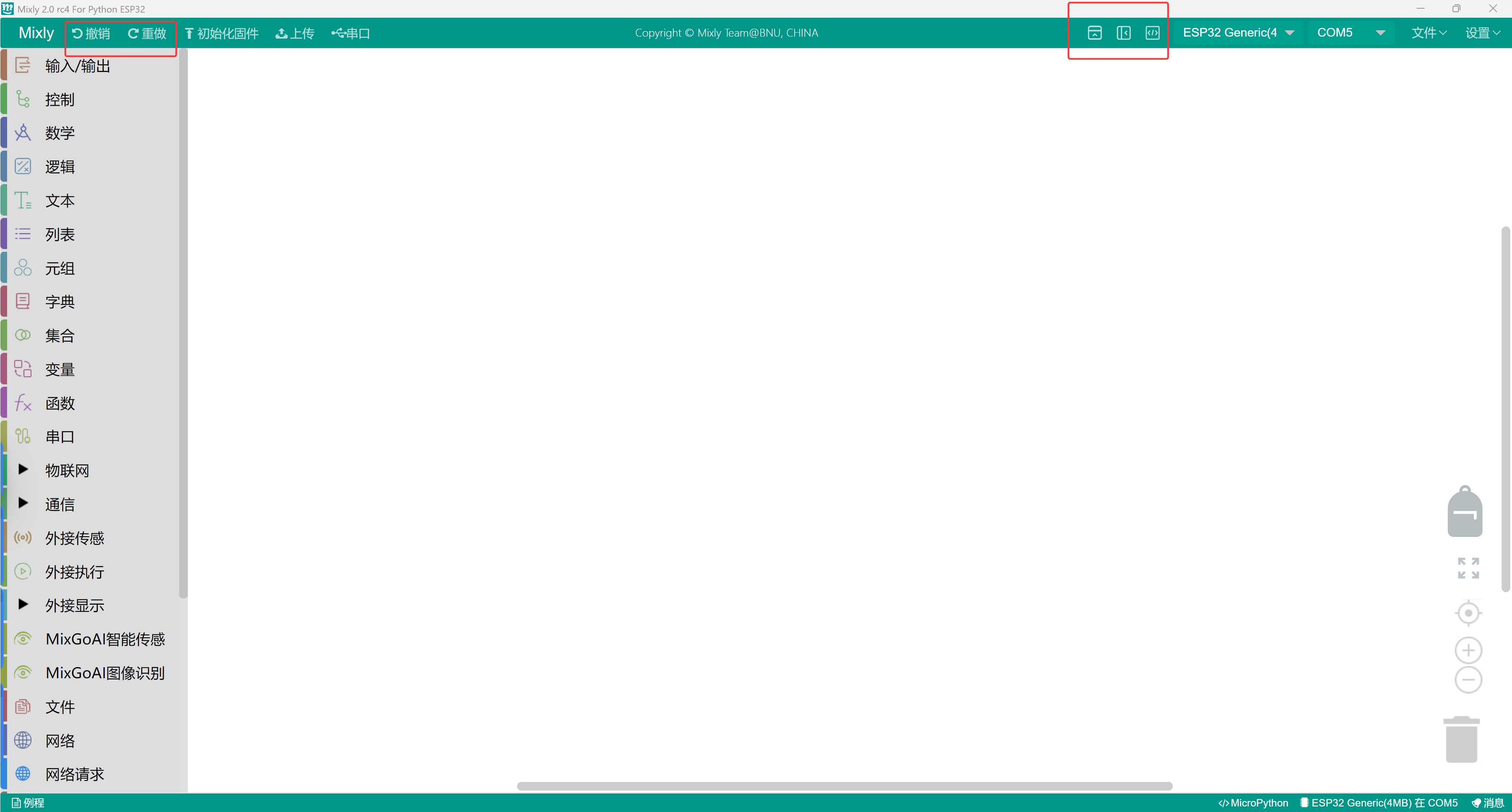
Function switch
Language switch: You can also switch the display language in the settings at the top right of the area.
Theme Switch: In the settings, the theme can be switched between normal view and advanced view to switch between views.
Programming Mode Switch: In the settings, the code can be switched to change the programming mode.
Undo/Redo: The undo function is available when a module is mistakenly deleted while writing code, and you can click the left arrow or press Ctrl+Z directly to restore the mistakenly deleted code; redo is the opposite of Ctrl+Z.
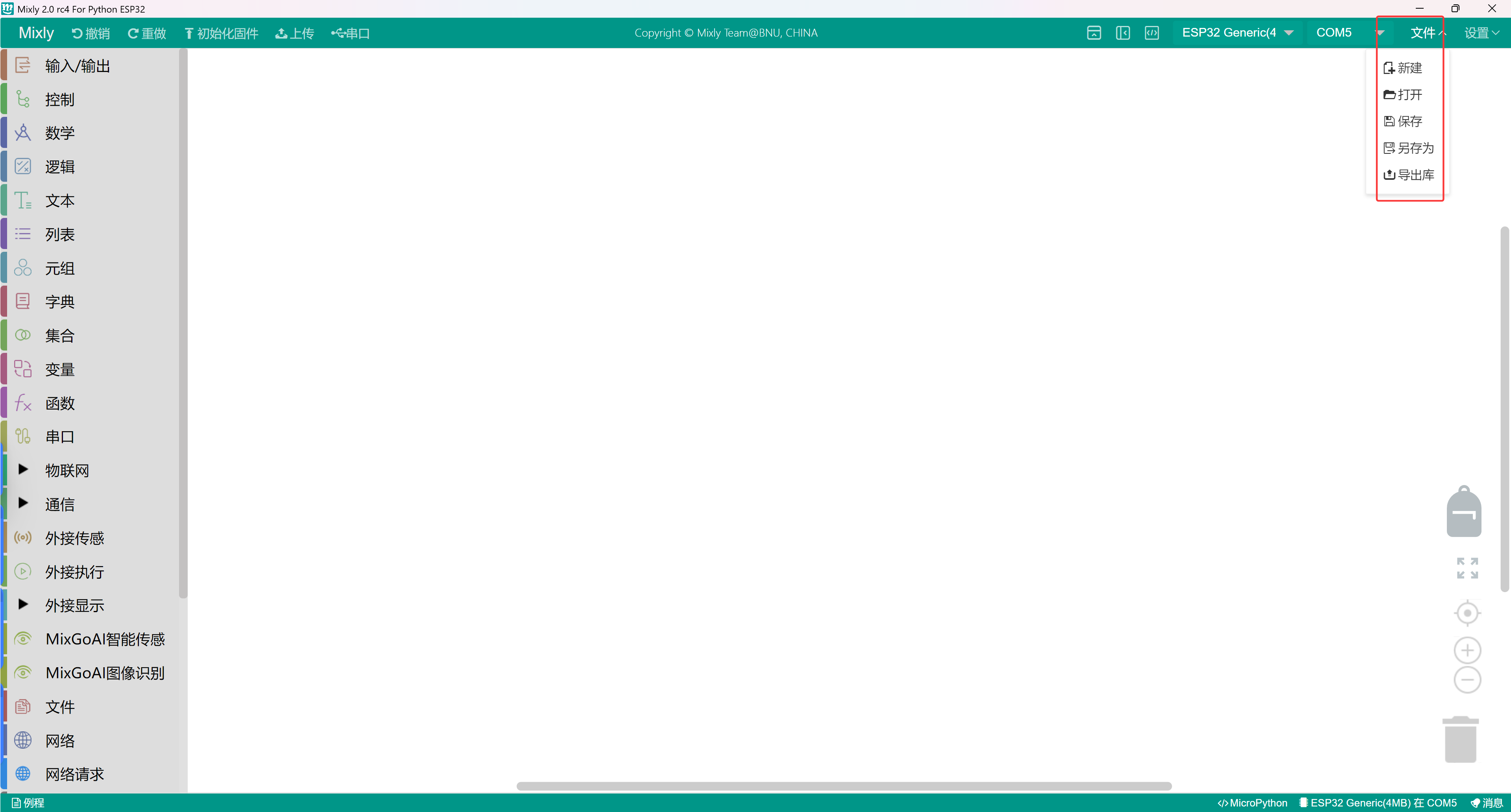
File Operation Area
New: Create Project File
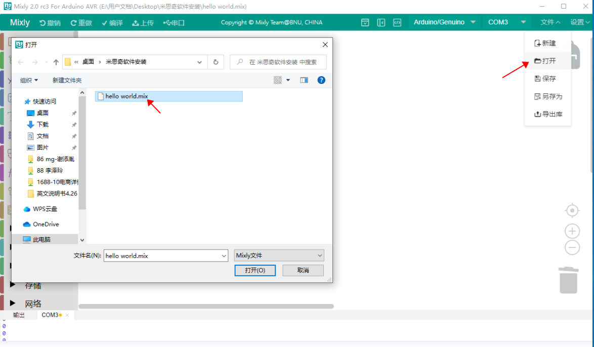
Open: Open Project File
Save: Save Project File
Save As: Save Project File As
Export Library: Export the current project as a library file
Import Library: Import the third library file
Manage Library: Operations such as deleting and renaming libraries
Library files are for convenient code sharing. Integrating a function into a single function. After exporting the library file, it can be shared with others.
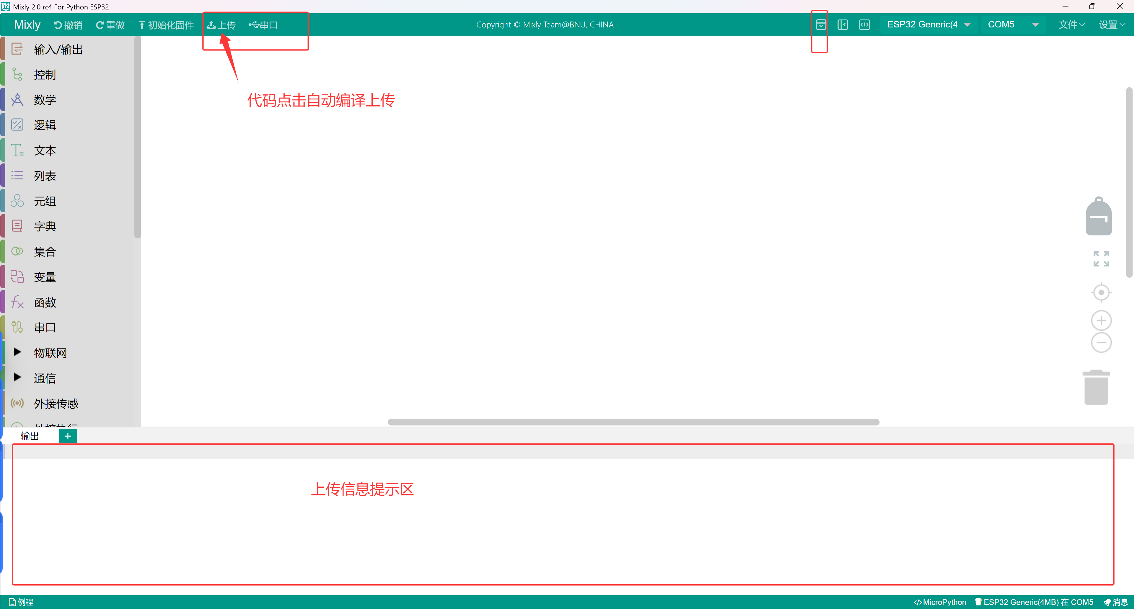
Code area

Program download and serial port monitoring
Compile: The program is compiled into machine executable code. The compilation process and results will be displayed in the information display area.
Motherboard Selection: Select the type of motherboard and the connected ports.
Serial port monitoring: Used to monitor information sent from the motherboard via the serial port or to send information to the motherboard. Requires programming. Mainly used for debugging programs or displaying information.
Note: It is essential to connect the module before uploading the code. Otherwise, an error will occur! It should be noted that the serial port monitor window should be closed when uploading the program. Otherwise, the program upload will fail.
5. Example program upload
Click on the mixly icon on the computer desktop to open the software, select Python ESP32
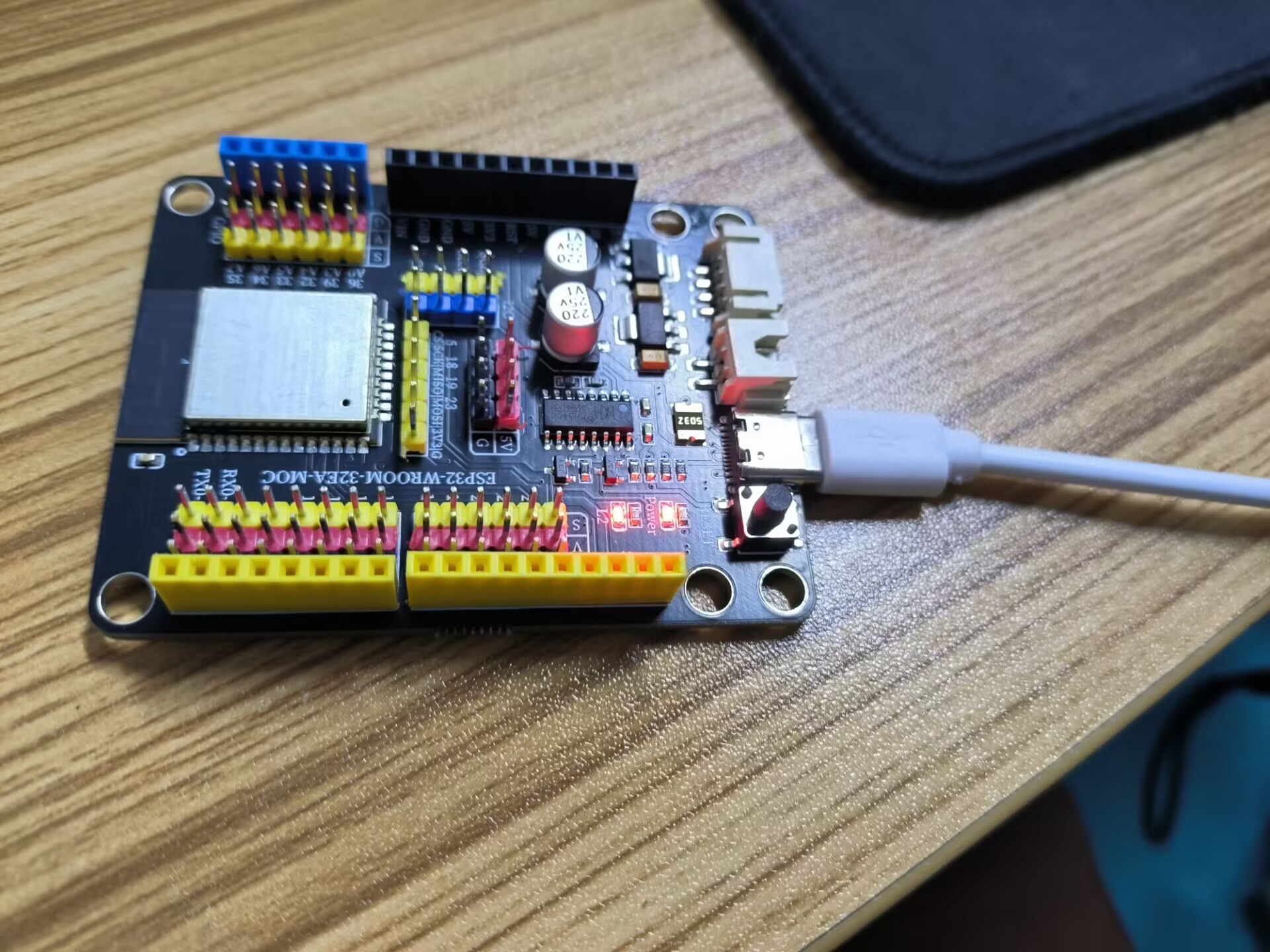
Use a USB data cable to connect the ESP32 development board to the computer. The red power indicator light should turn on.
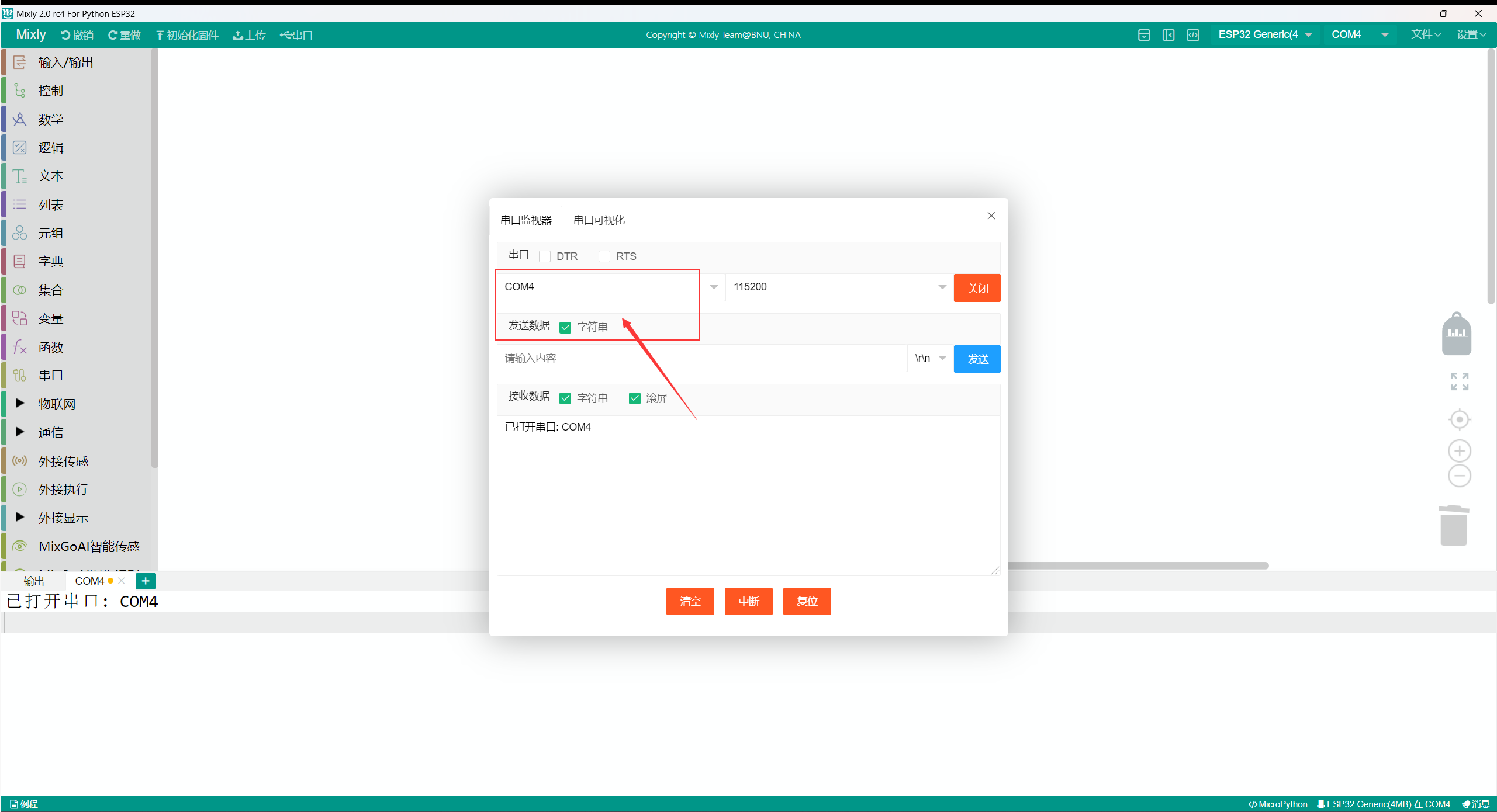
Choose the correct hardware and port (choose ESP32 Gemeric (4MB) and com port).If the port is COM3 or a higher version port (COM1 and COM2 are usually reserved for hardware serial ports).To find the answer, you can disconnect the ESP32 development board and reconnect it to the computer; the disappeared COM port is the COM port of the ESP32 development board.Reconnect the motherboard and select this serial port.Here, you should select COM 4 as shown.
If Mixly does not recognize the USB port:
1. Have you installed the USB to serial port driver CH341SER?
2. Is the USB cable in good condition?
3. Is the USB cable connected to the computer's UBS interface?
Attention: To avoid errors, the COM port should match the port displayed in the Device Manager.
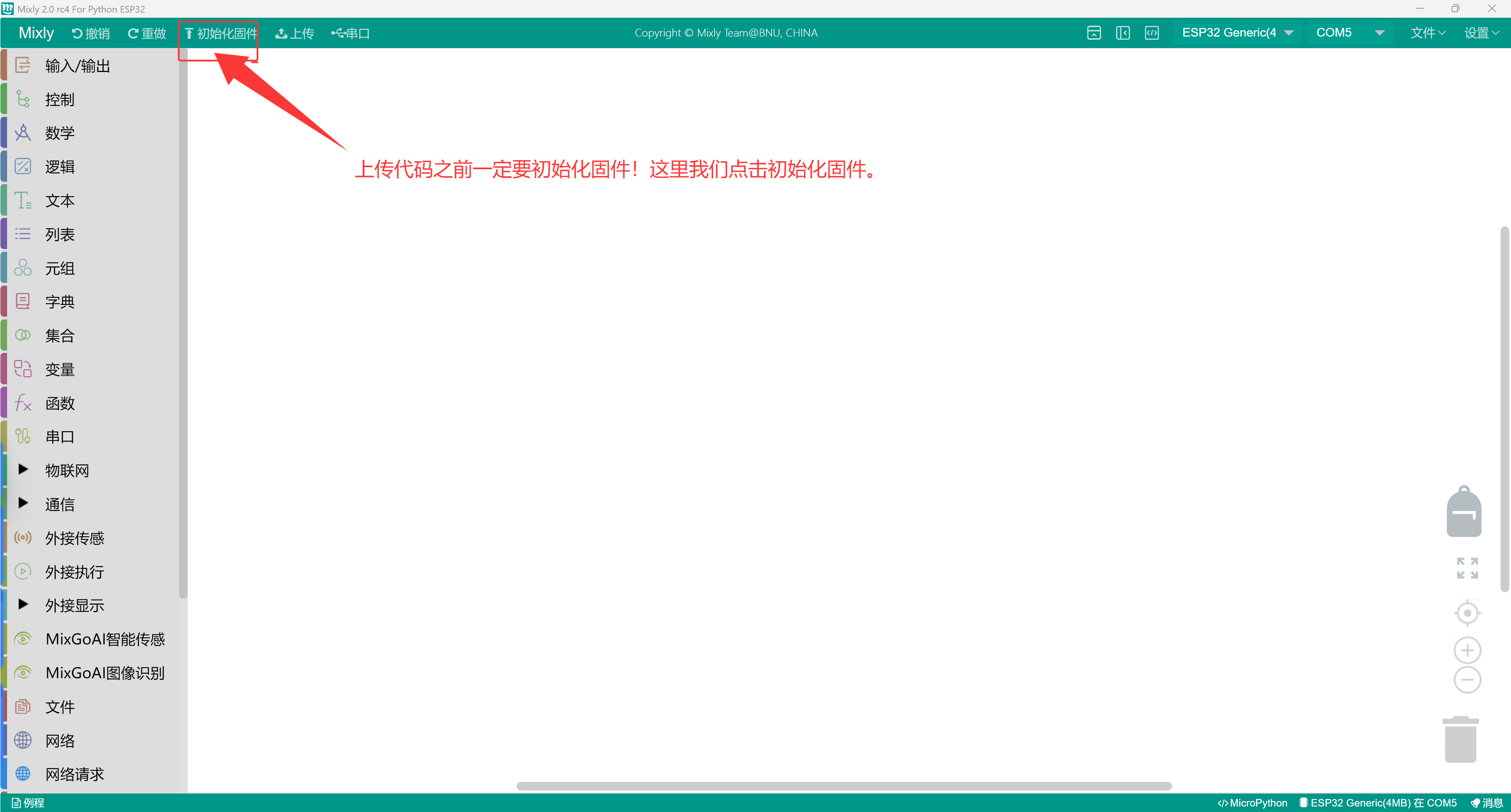
Upload programClick to download the example program
This is an example program that displays Hello STEM!
Click to upload the program.
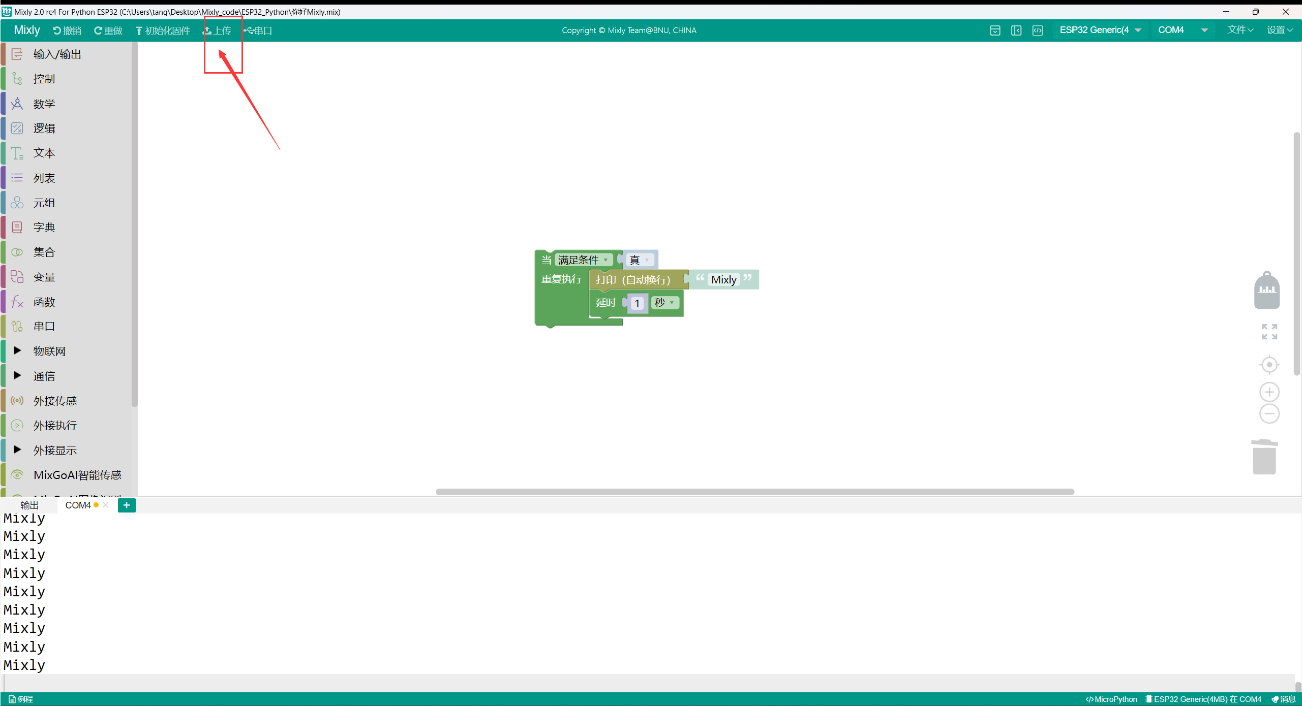
Open the serial monitor.
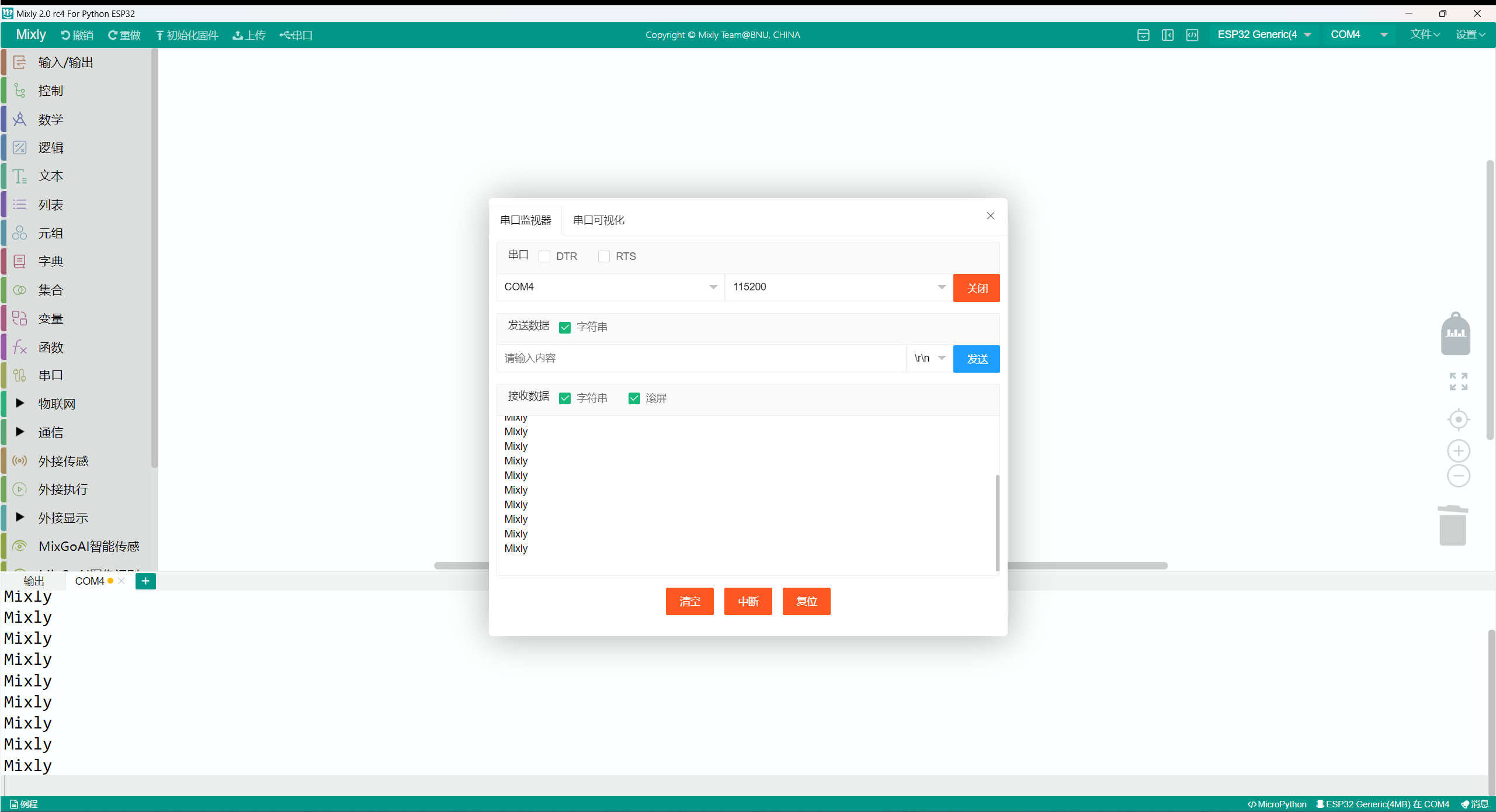
You can see that Mixly keeps printing.
Mac system Mixly installation package:https://mp.weixin.qq.com/s/ntaD-eYdjlEXlMMaHOtBAQ