
1. Introduction
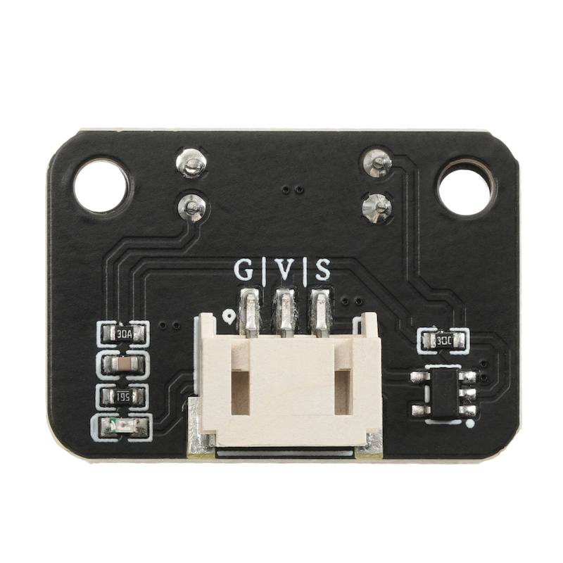
The shaft encoder counting sensor uses a slot type through-beam photoelectric sensor, which is composed of an infrared LED and an NPN photoelectric triode, with a slot width of 5.9MM.As long as the opaque object passes through the slot, it can trigger the output TTL low level.Using a Schmidt trigger to debounce the pulse, it is very stable and can be used for applications such as measuring the speed and distance of small cars, etc.
2. Schematic
Encoder Counting Sensor-HS-S58P SchematicClick to view
Module Parameters
Pin Name | description |
|---|---|
G | GND (Negative Power Input) |
V | VCC (Positive Power Input) |
S | Microcontroller Signal Pin |
Power Supply Voltage: 3.3V / 5V
Connection Method: PH2.0 Terminal Wire
Installation Method: Double Screw Fixed
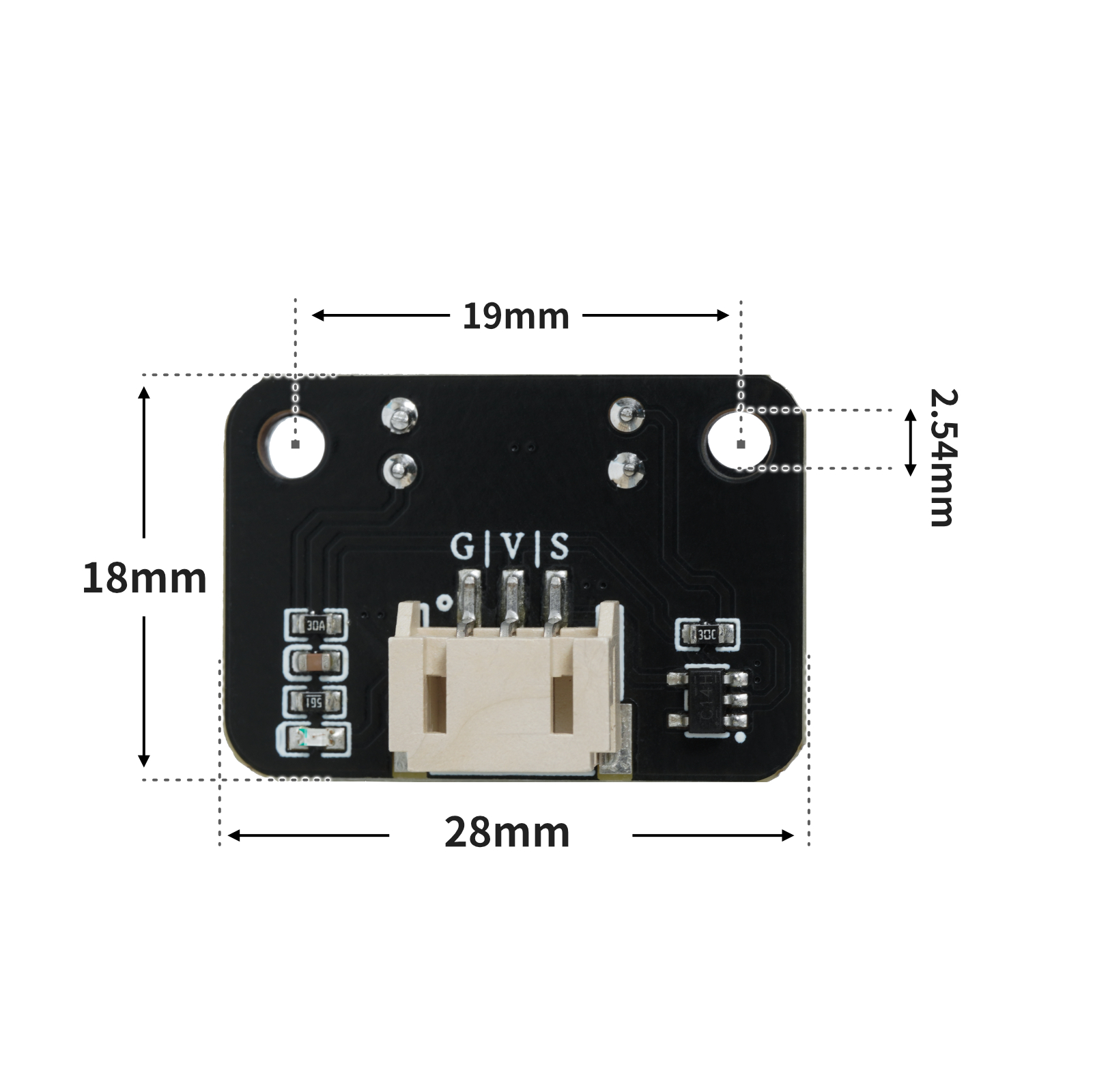
4, Circuit Board Size
5 of Arduino IDE example program
Attention: If prompted with an error message about the library file during program upload, please import the library file first!
Arduino IDE Library Download and Import Tutorial:Click to view
Example program (UNO development board):
volatile float Val;
volatile float time;
volatile float Speed;
volatile float Speed1;
volatile float Val1;

void attachInterrupt_fun_CHANGE_2() {
  count();
}

void count() {
  Val = Val + 1;
}

void setup(){
  Serial.begin(9600);
  Val = 0;
  time = 0;
  Speed = 0;
  Speed1 = 0;
  Val1 = 0;
  pinMode(2, INPUT);
  attachInterrupt(digitalPinToInterrupt(2),attachInterrupt_fun_CHANGE_2,CHANGE);
}

void loop(){
  //电机测速:20孔码盘,单位转/分

  String("转速:") + String(Speed);

  time = millis();
  Speed = (Val / 40) / (time / 60000);
  Serial.println(digitalRead(2));

}
6, ESP32 Python Example (for Mixly IDE/Misashi)
Choose the development board Python ESP32 [ESP32 Generic(4MB)] and upload in code mode
Attention: If prompted with an error message about the library file during program upload, please import the library file first!
Download and import tutorial for Mixly IDE ESP32 library:Click to view
Example program (ESP32-Python):
import machine
import time
def attachInterrupt_func(x):
global val
val = val + 1
pass
val = 0
pin2 = machine.Pin(2, machine.Pin.OUT)
pin4 = machine.Pin(4, machine.Pin.OUT)
machine.Pin(12).irq(handler = attachInterrupt_func, trigger = (machine.Pin.IRQ_RISING | machine.Pin.IRQ_FALLING))
pin2.value(1)
pin4.value(1)
t = float(0)
speed = float(0)
while True:
t = time.ticks_ms()
speed = (val / 40) / (t / 60000)
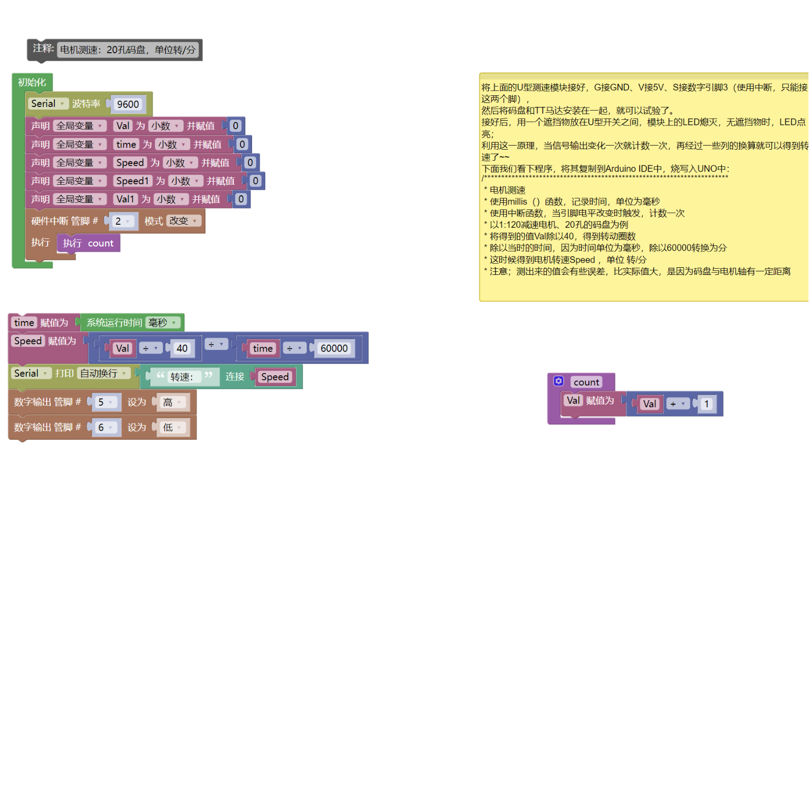
print(speed)7, Mixly example program (graphical language)
Example program (UNO development board):Click to download
Attention: If prompted with an error message about the library file during program upload, please import the library file first!
Download and import tutorial of Mixly IDE Arduino library:Click to view
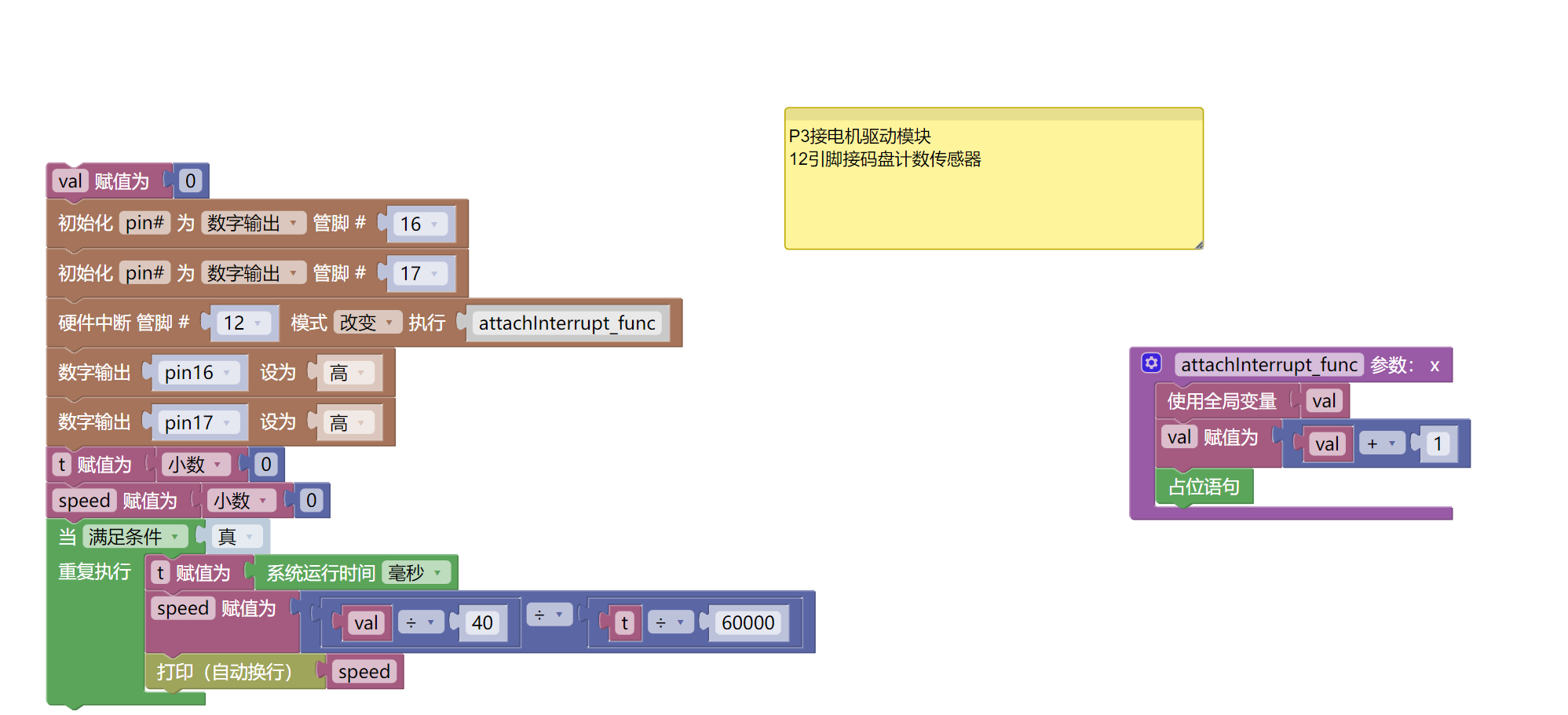
Example Program (ESP32 Development Board):Click to download
Attention: If prompted with an error message about the library file during program upload, please import the library file first!
Download and import tutorial for Mixly IDE ESP32 library:Click to view
8. Setting up the Test Environment
Arduino UNO Test Environment Setup
Prepare Components:
HELLO STEM UNO R3 DEVELOPMENT BOARD *1
HELLO STEM UNO EXP1 Expansion Board *1
USB TYPE-C DATA CABLE *1
Encoder Counting Sensor (HS-S58P) *1
Motor Driver Module (HS-F04P) *1
PH2.0 3P double-ended terminal line *2 or PH2.0 3P connector to DuPont wire *2
Circuit wiring diagram:
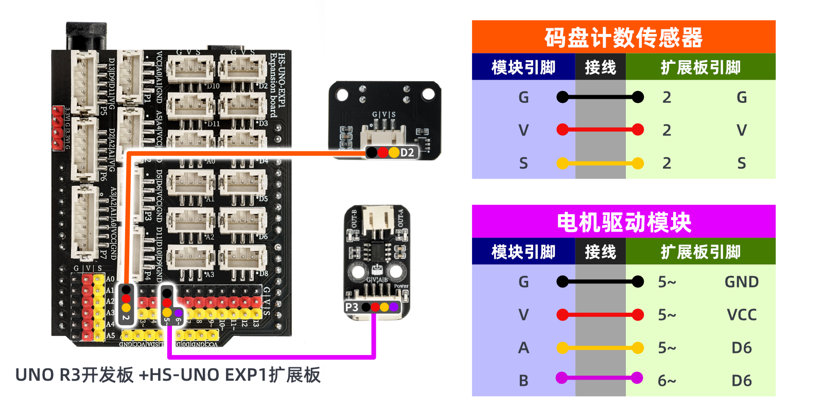
ESP32 Test Environment Setup
Prepare Components:Pending update...
Circuit wiring diagram:Pending update...
9, Video tutorial
Video tutorial:Click to view
10, Test results
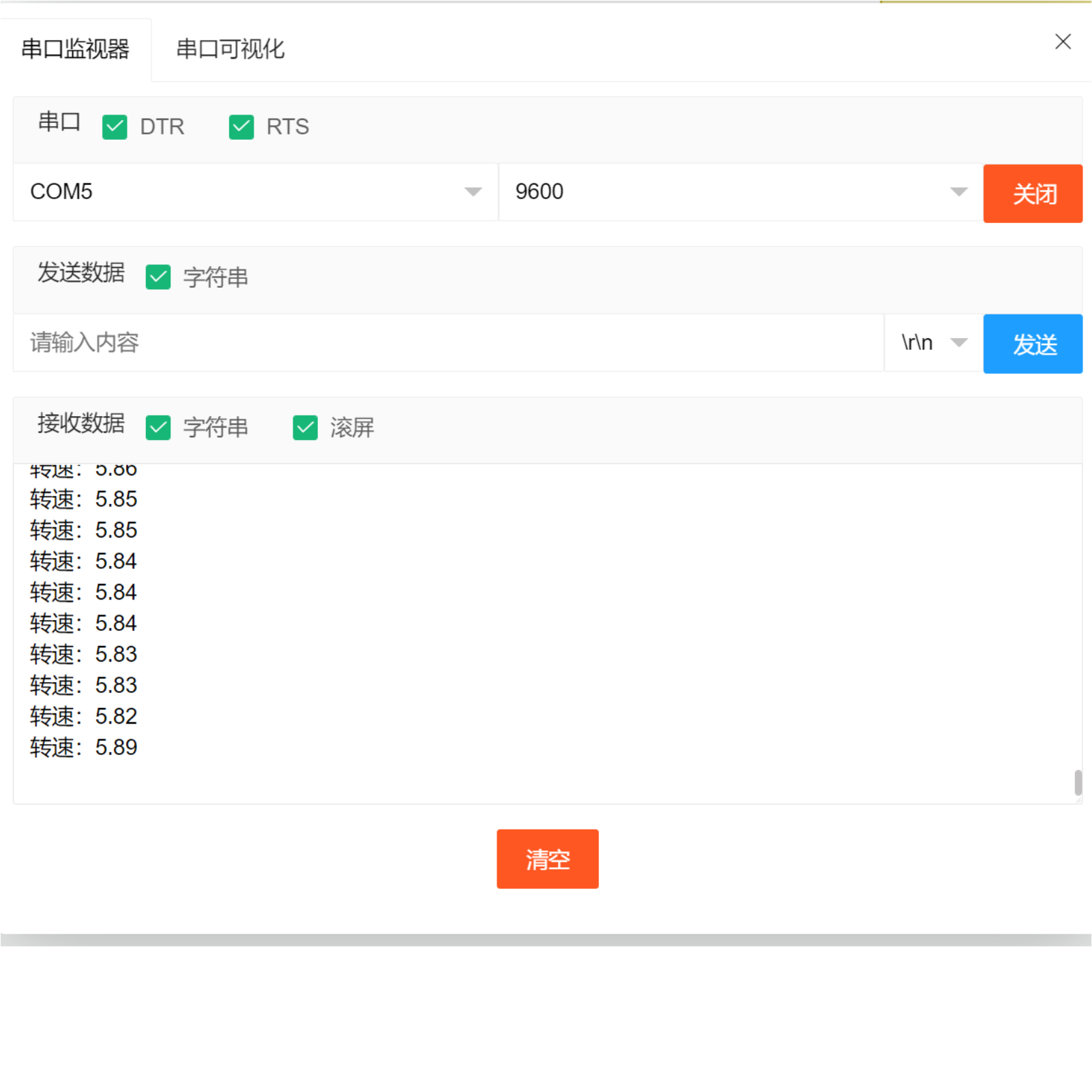
Arduino UNO test results:
After the device is connected to the wires, burn the above program to the UNO-R3PRO development board and then connect the power supply.Open the serial port monitor, and you will see the speed data when the encoder counting sensor detects an impact signal.
ESP32 Test Results:
Pending update...