
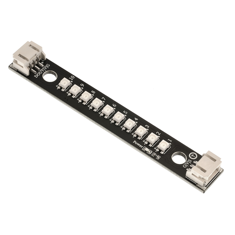
1. Introduction
2. Schematic
RGB-LED lamp-HS-F12-L schematicClick to view
Module Parameters
Pin Name | description |
|---|---|
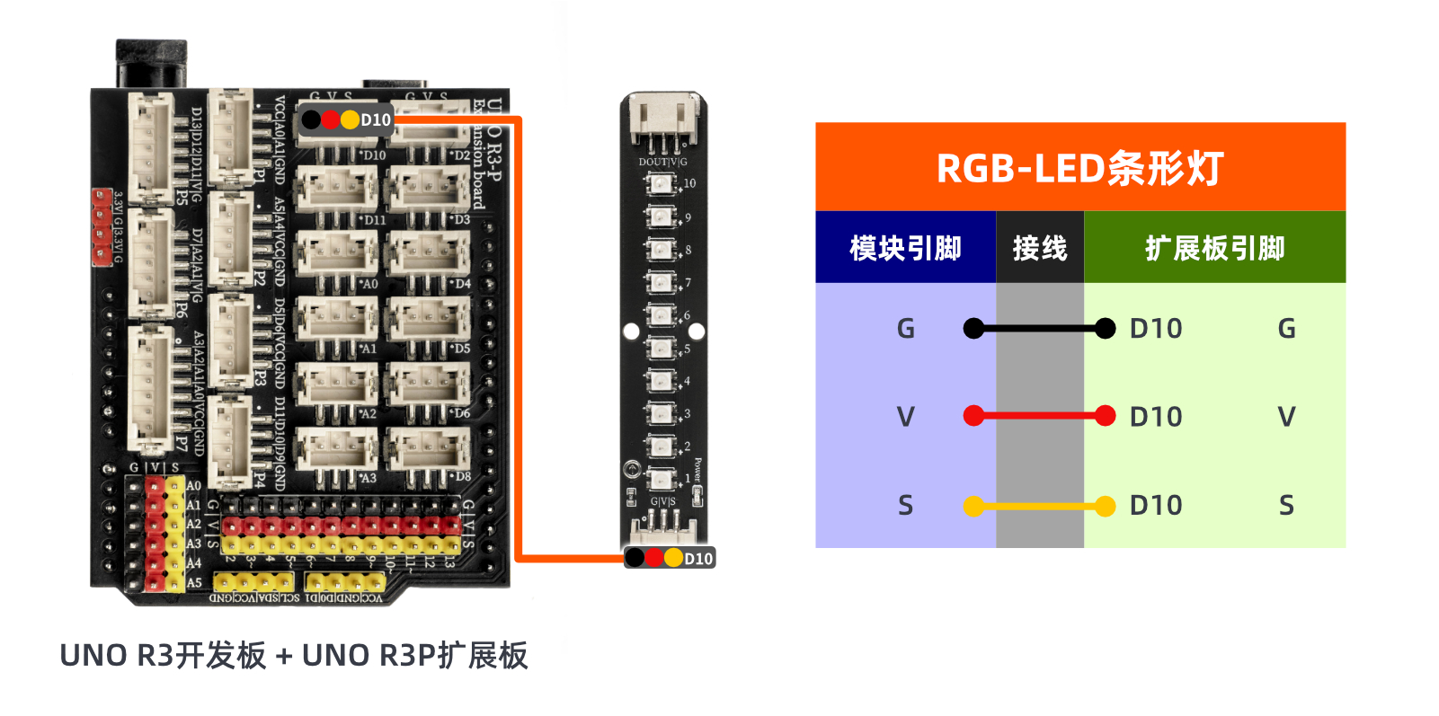
G | Negative Pole of Power |
V | Positive Pole of Power |
S | Digital Signal Pin |
D(DOUT) | The signal output can be connected to the next LED bead |
Power Supply Voltage: 3.3V / 5V
Connection method: PH2.0 terminal wire
Installation method: Screw fixed / Lego construction
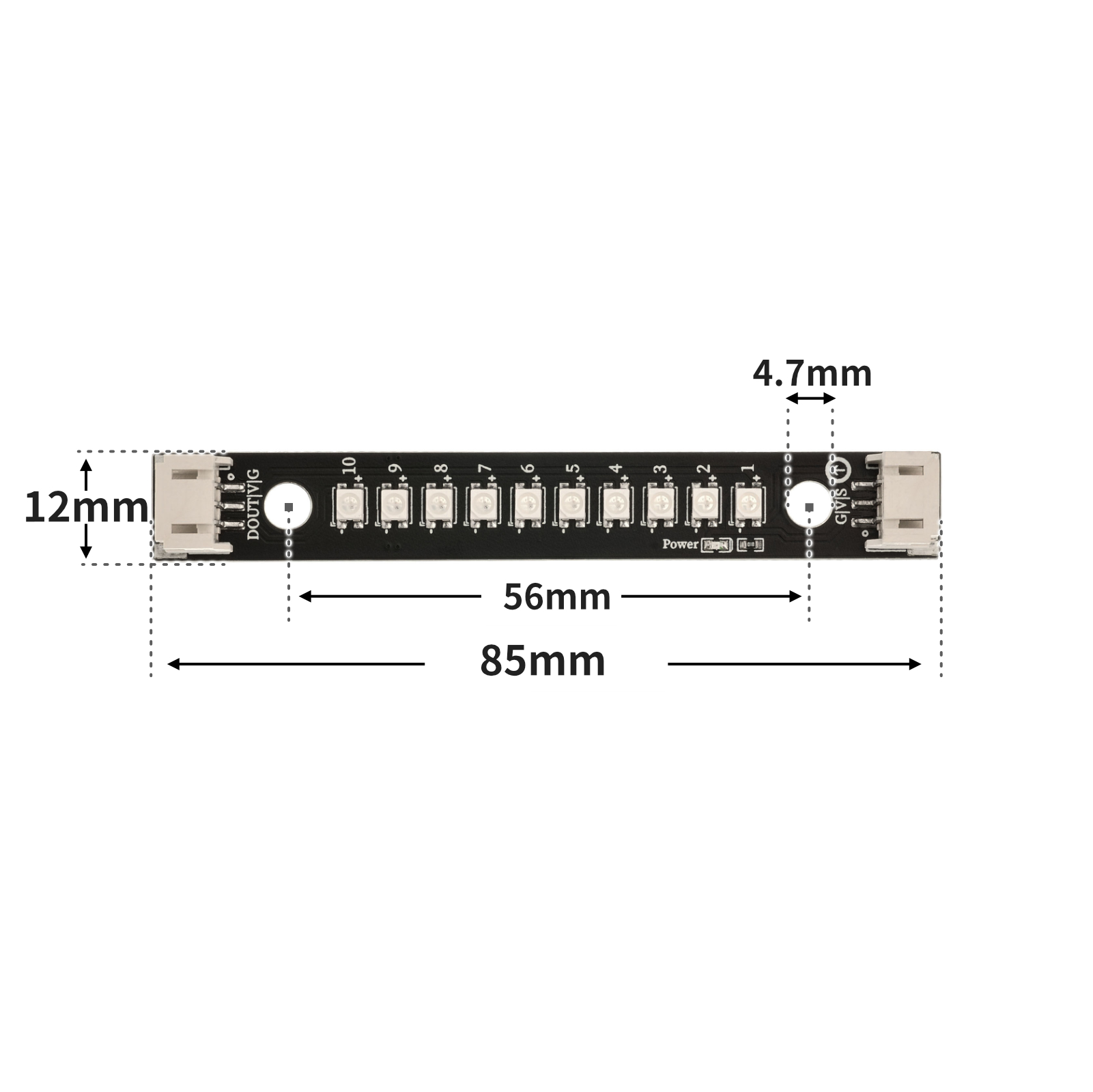
4, Circuit Board Size
5 of Arduino IDE example program
Attention: If prompted with an error message about the library file during program upload, please import the library file first!
Arduino IDE Library Download and Import Tutorial:Click to view
Example program (UNO development board):
#include <Adafruit_NeoPixel.h>

Adafruit_NeoPixel rgb_display_10 = Adafruit_NeoPixel(12,10,NEO_GRB + NEO_KHZ800);

void setup(){
  rgb_display_10.begin();
}

void loop(){
  for (int i = 1; i <= 12; i = i + (1)) {
    rgb_display_10.setPixelColor((i)-1, ((((i * 21) & 0xffffff) << 16) | ((0 & 0xffffff) << 8) | 0));
    rgb_display_10.show();
    delay(200);
    rgb_display_10.setPixelColor((i)-1, (0xffff00));
    rgb_display_10.show();
    delay(200);
  }

}
6, ESP32 Python Example (for Mixly IDE/Misashi)
Choose the development board Python ESP32 [ESP32 Generic(4MB)] and upload in code mode
Attention: If prompted with an error message about the library file during program upload, please import the library file first!
Download and import tutorial for Mixly IDE ESP32 library:Click to view
Example program (ESP32-Python):
import machine
import neopixel
import time
rgb = neopixel.NeoPixel(machine.Pin(2), 12)
while True:
for i in range(0, 12, 1):
rgb[i] = (100, 0, 0)
rgb.write()
time.sleep(1)
for i in range(0, 12, 1):
rgb[i] = (0, 0, 0)
rgb.write()
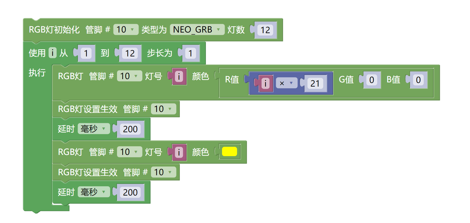
time.sleep(1)7, Mixly example program (graphical language)
Example program (UNO development board):Click to download
Attention: If prompted with an error message about the library file during program upload, please import the library file first!
Download and import tutorial of Mixly IDE Arduino library:Click to view
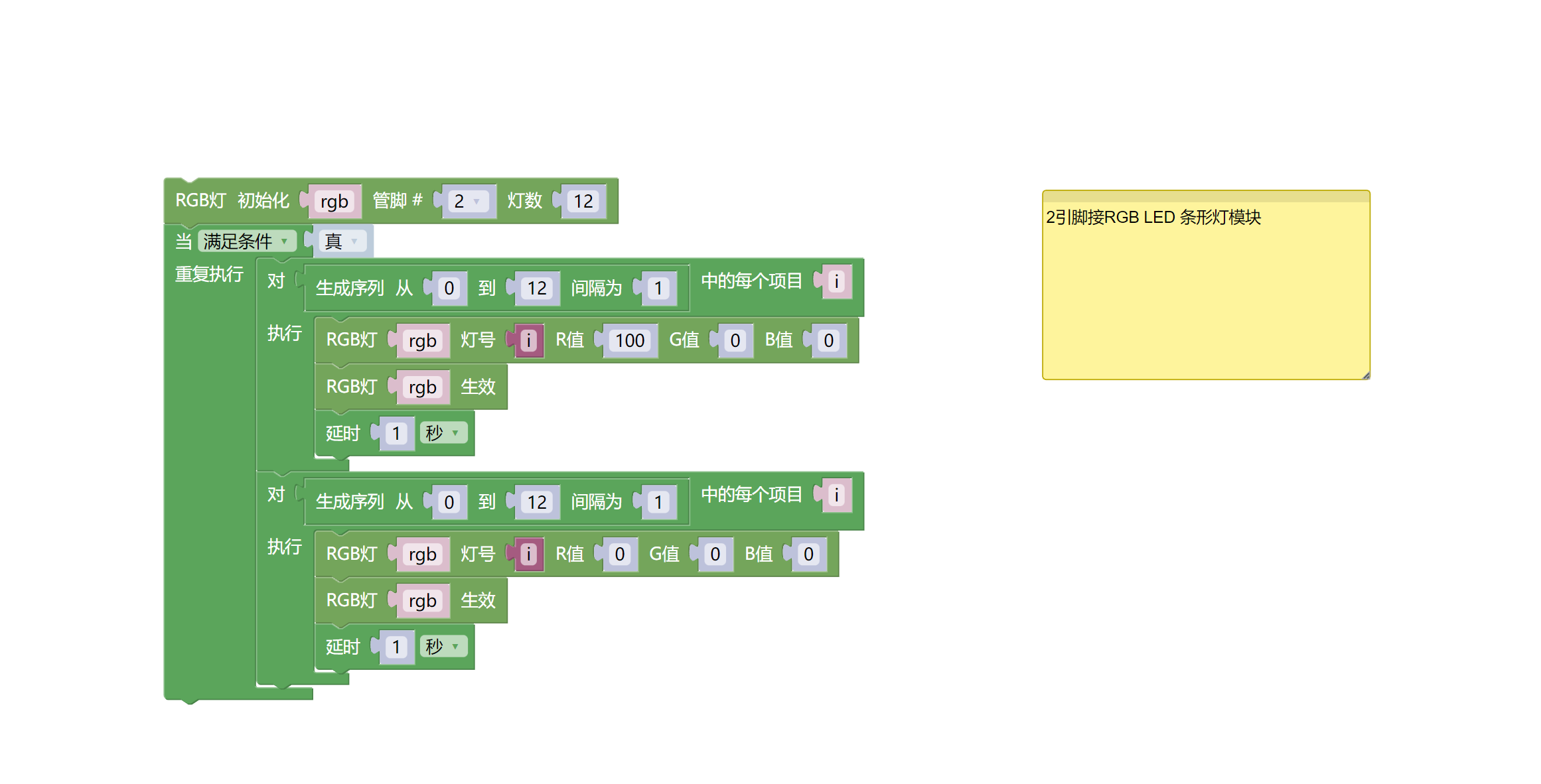
Example Program (ESP32 Development Board):Click to download
Attention: If prompted with an error message about the library file during program upload, please import the library file first!
Download and import tutorial for Mixly IDE ESP32 library:Click to view
8. Setting up the Test Environment
Arduino UNO Test Environment Setup
Prepare Components:
HELLO STEM UNO R3 DEVELOPMENT BOARD *1
HELLO STEM UNO R3 P EXPANSION BOARD *1
USB TYPE-C DATA CABLE *1
RGB LED Ring Module (HS-F12P) *1
PH2.0 3P Connector to DuPont Wire *1 or PH2.0 3P Dual Head Connector Wire *1
Circuit wiring diagram:
ESP32 Test Environment Setup
Prepare Components:Pending update...
Circuit wiring diagram:Pending update...
9, Video tutorial
Arduino UNO video tutorial:Click to view
ESP32 Python Video Tutorial:Click to view
10, Test results
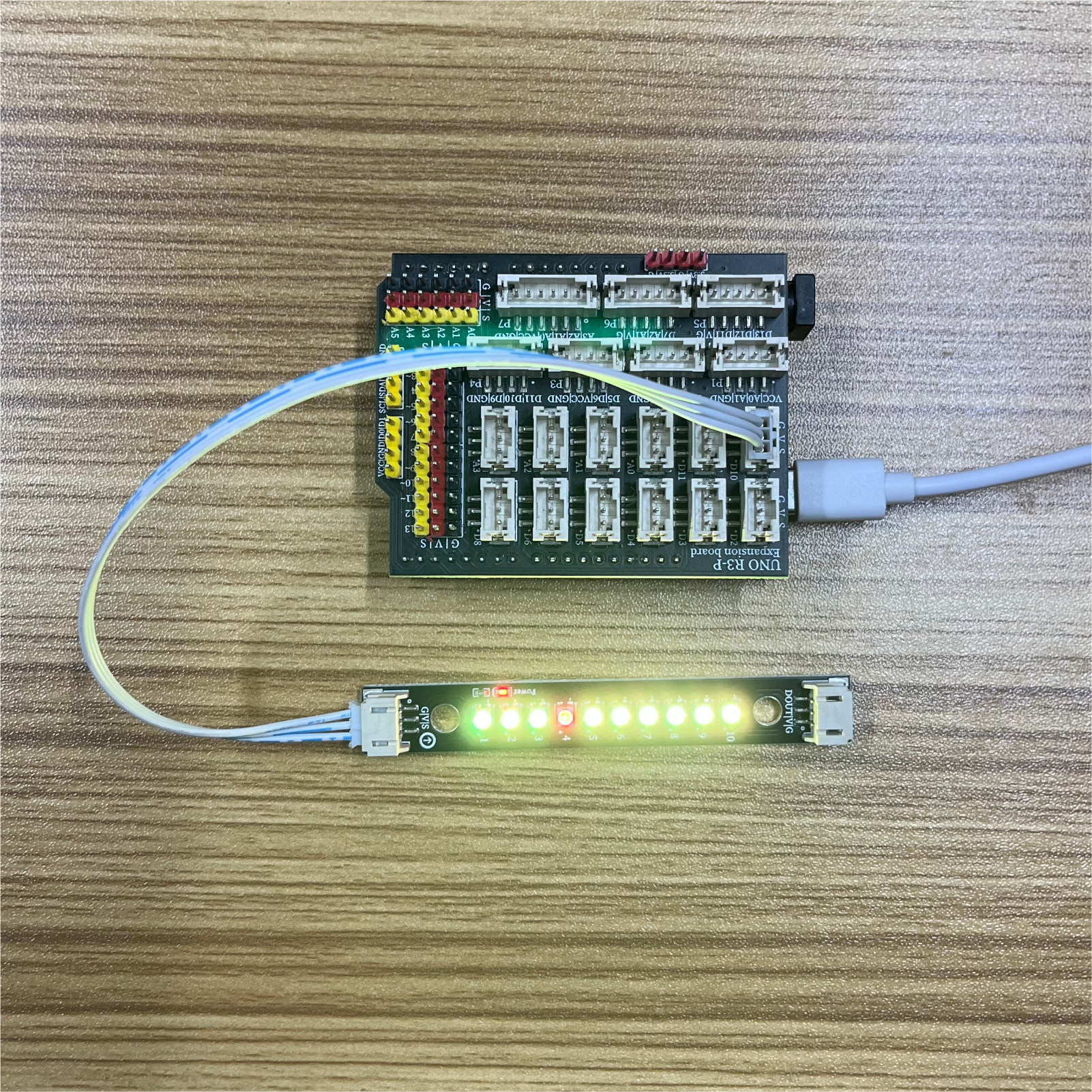
Arduino UNO Test Conclusion:
After the device is connected to the wire, upload the above program to the Arduino UNO development board, and you will see the lights on the ring light up one by one in yellow. After each light is lit, it will pass the red light, creating a running light effect.
ESP32 Python test conclusion:
After the device is connected to the wire, upload the above program to the Arduino UNO development board, and you will see the lights on the ring light up one by one in yellow. After each light is lit, it will pass the red light, creating a running light effect.