
1. Introduction
When a high-level signal is present at the signal input terminal, the common terminal will conduct with the normally open terminal.
Can directly control various devices and loads.
Has power and relay action indication, bright when closed, not bright when open.
Has one normally open and one normally closed contact.
Control DC or AC signals, can control 220V AC load.
2. Schematic
Relay module-HS-F17P schematicClick to view
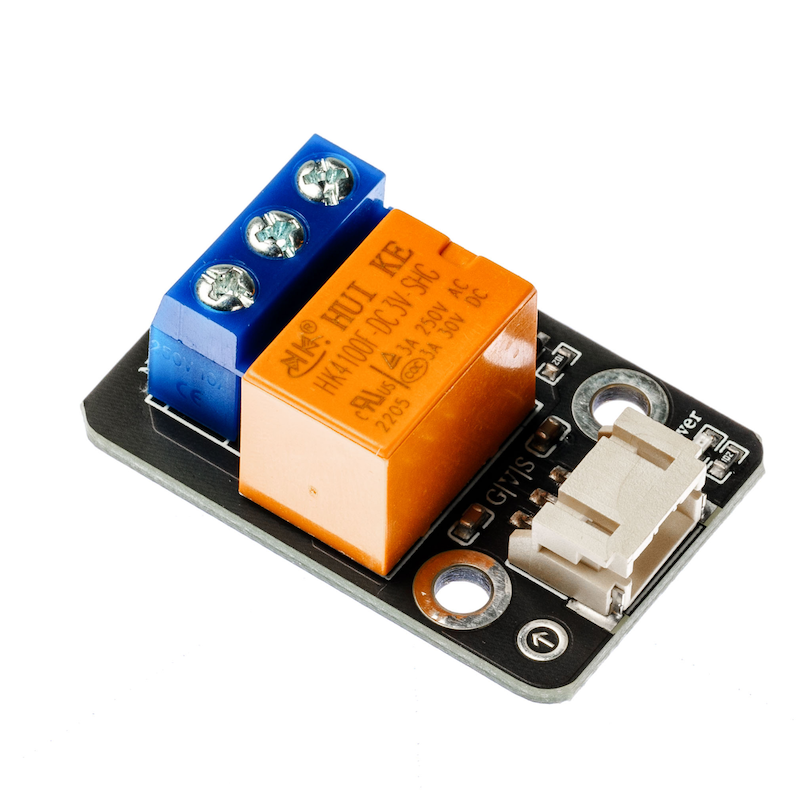
Module Parameters
Pin Name | description |
|---|---|
G | GND ground wire |
V | 5V power pin |
S | Digital Signal Pin |
COM | Common terminal |
ON | Normally open terminal |
NC | Normally closed terminal |
Power Supply Voltage: 3.3V / 5V
Connection type: PH2.0 3P terminal wire
Installation Method: Double Screw Fixed
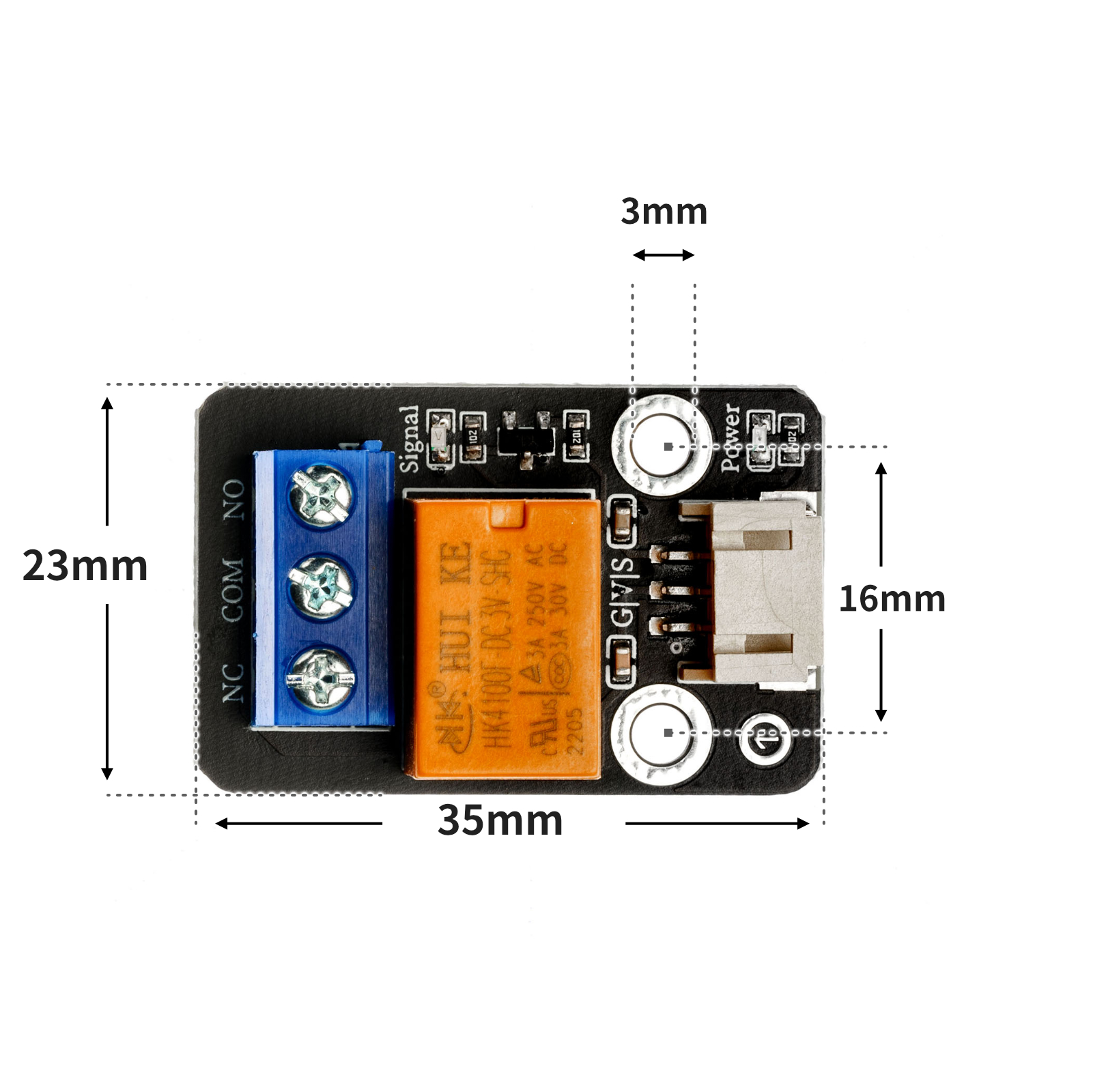
4, Circuit Board Size
5 of Arduino IDE example program
Attention: If prompted with an error message about the library file during program upload, please import the library file first!
Arduino IDE Library Download and Import Tutorial:Click to view
Example program (UNO development board):
void setup(){
 pinMode(6, OUTPUT);
}
void loop(){
 //继电器接D6
 digitalWrite(6,HIGH);
 delay(1000);
 digitalWrite(6,LOW);
 delay(1000);
}
6, ESP32 Python Example (for Mixly IDE/Misashi)
Choose the development board Python ESP32 [ESP32 Generic(4MB)] and upload in code mode
Attention: If prompted with an error message about the library file during program upload, please import the library file first!
Download and import tutorial for Mixly IDE ESP32 library:Click to view
Example program (ESP32-Python):
import machine
import time
pin2 = machine.Pin(2, machine.Pin.OUT)
while True:
pin2.value(1)
time.sleep(1)
pin2.value(0)
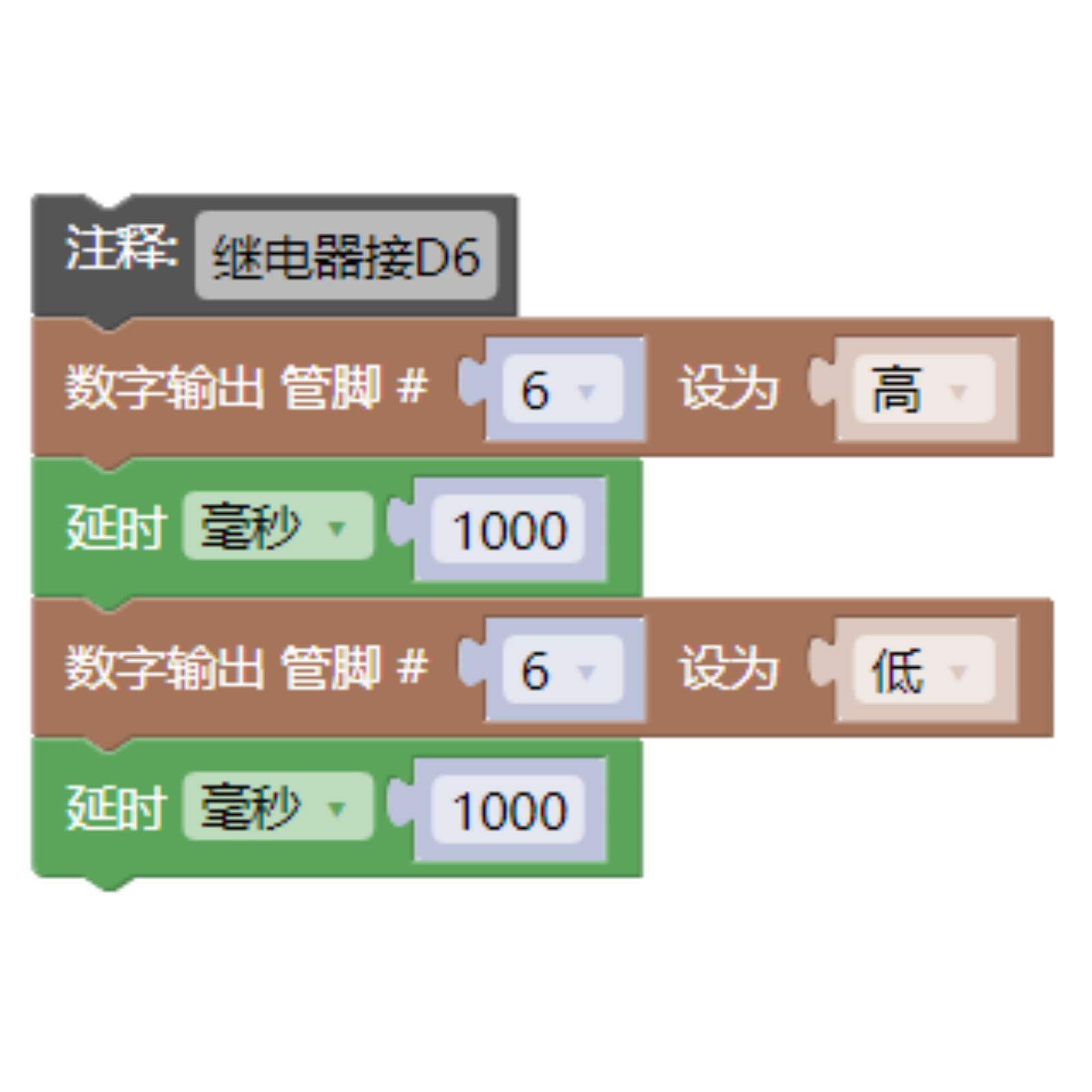
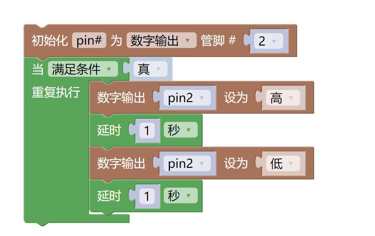
time.sleep(1)7, Mixly example program (graphical language)
Example program (UNO development board):Click to download
Attention: If prompted with an error message about the library file during program upload, please import the library file first!
Download and import tutorial of Mixly IDE Arduino library:Click to view
Example Program (ESP32 Development Board):Click to download
Attention: If prompted with an error message about the library file during program upload, please import the library file first!
Download and import tutorial for Mixly IDE ESP32 library:Click to view
8. Setting up the Test Environment
Arduino UNO Test Environment Setup
Prepare Components:
HELLO STEM UNO R3 DEVELOPMENT BOARD *1
HELLO STEM UNO R3 P EXPANSION BOARD *1
USB TYPE-C DATA CABLE *1
Relay Module (HS-F17P) *1
PH2.0 3P Connector to DuPont Wire *1 or PH2.0 3P Dual Head Connector Wire *1
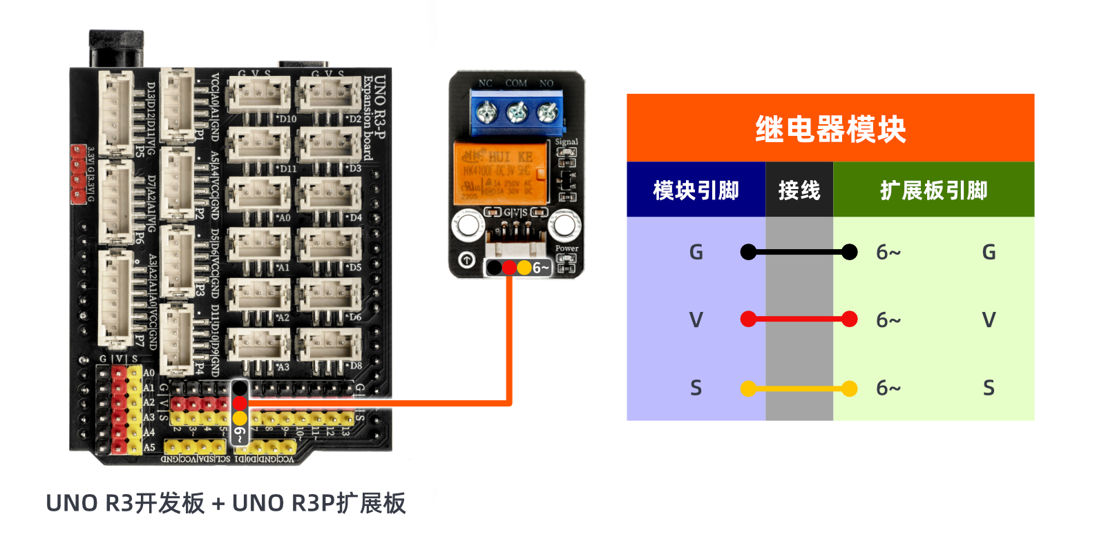
Circuit wiring diagram:
ESP32 Test Environment Setup
Prepare Components:Updated with...
Circuit wiring diagram:Updated with...
9, Video tutorial
Video tutorial:Click to view
10, Test conclusion
Arduino UNO test results:
After the device is wired up, upload the above program to the Arduino UNO development board. When the relay contacts close, the signal light turns on; when they are disconnected, the signal light goes out.
ESP32 Test Results:
Pending update...