1. Introduction
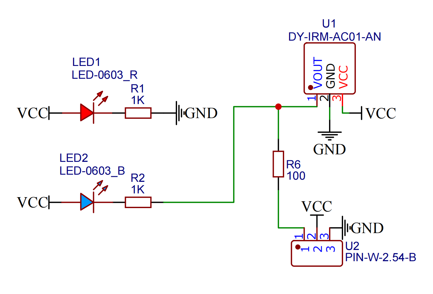
2. Schematic
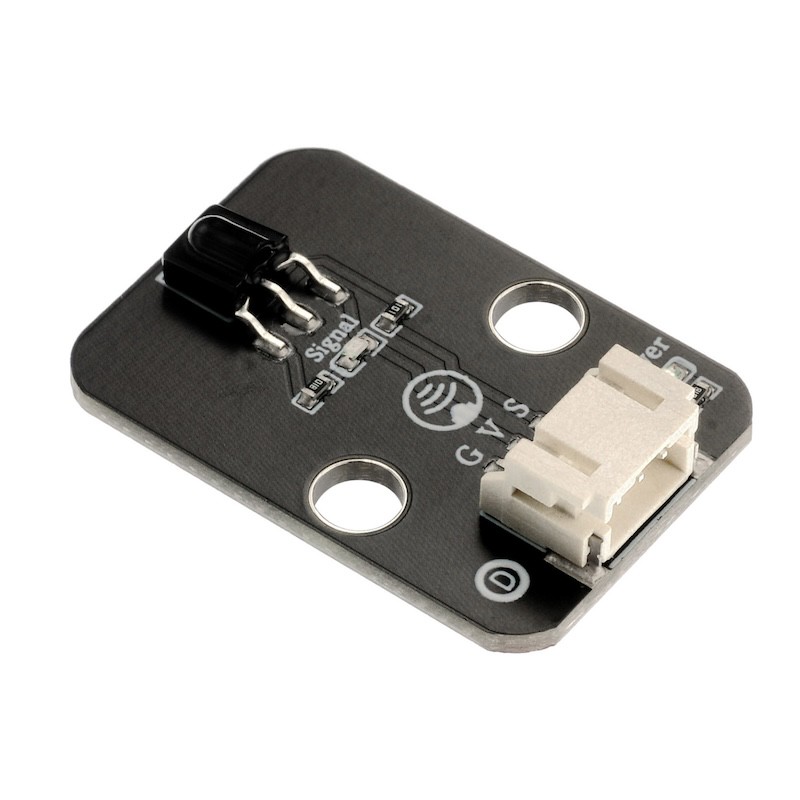
Module Parameters
Pin Name | description |
|---|---|
G | GND (Negative Power Input) |
V | VCC (Positive Power Input) |
S | Digital Signal Pin |
Power Supply Voltage: 3.3V / 5V
Connection method: PH2.0 socket
Installation method: Screw fixed / Lego construction
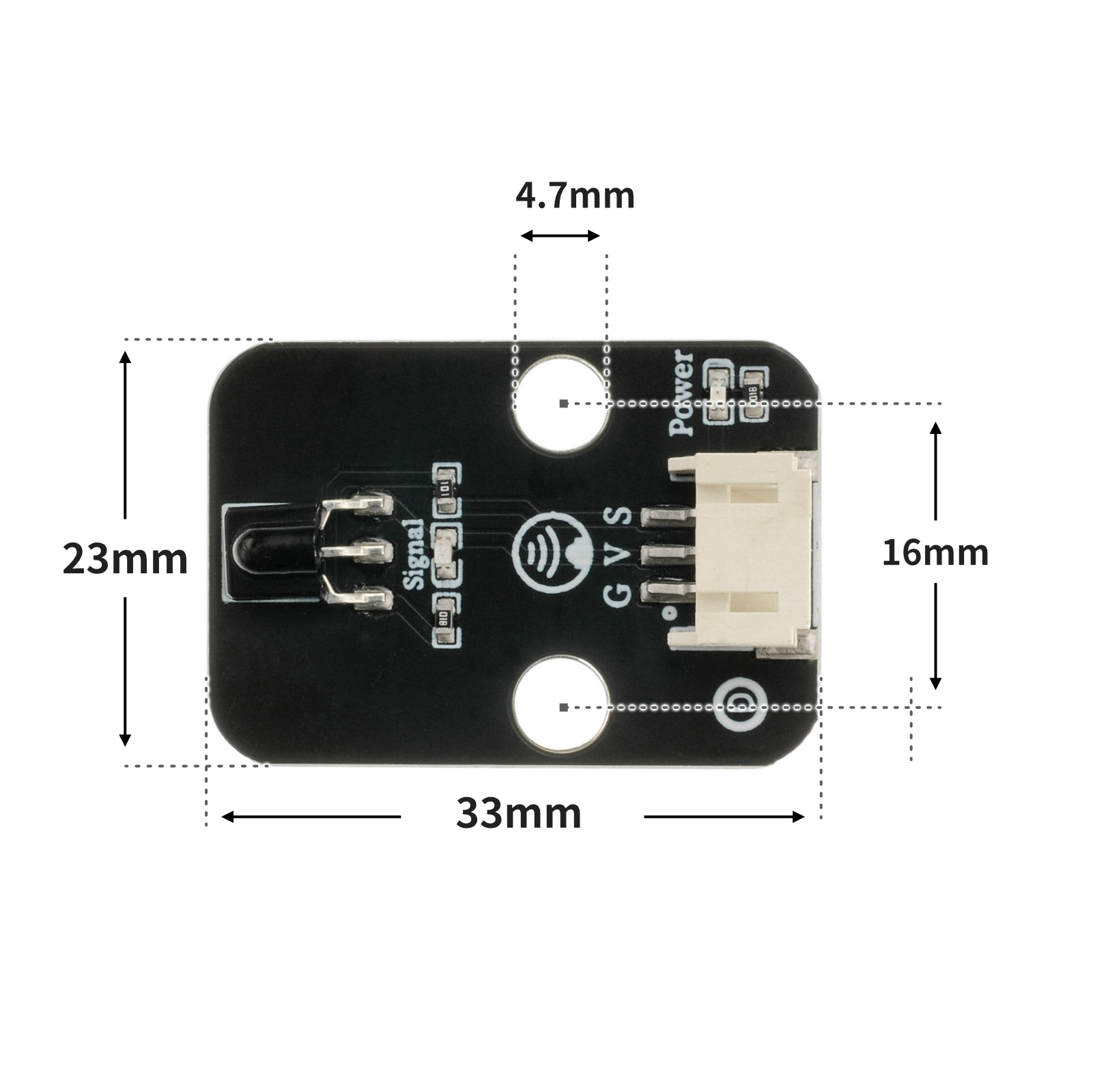
4, Circuit Board Size
5. Add Arduino library file
Reference here if you don't know how to use library files:Install and use library files
Library file:Click to download
6, Arduino IDE example program
Example Program (UNO Development Board):Click to download
/***********************************************************
文件名:17_IRremote.ino
描述:红外遥控灯。
作者:陈志强
日期:2022.11.3
***********************************************************/
#include <IRremote.h>
volatile int red;
volatile int yellow;
volatile int green;
const String IR_PROTOCOL_TYPE[] = {
"UNKNOWN",
"PULSE_DISTANCE",
"PULSE_WIDTH",
"DENON",
"DISH",
"JVC",
"LG",
"LG2",
"NEC",
"PANASONIC",
"KASEIKYO",
"KASEIKYO_JVC",
"KASEIKYO_DENON",
"KASEIKYO_SHARP",
"KASEIKYO_MITSUBISHI",
"RC5",
"RC6",
"SAMSUNG",
"SHARP",
"SONY",
"ONKYO",
"APPLE",
"BOSEWAVE",
"LEGO_PF",
"MAGIQUEST",
"WHYNTER"
};
IRrecv irrecv_4(4);
void setup(){
red = 11;
yellow = 10;
green = 9;
Serial.begin(9600);
irrecv_4.enableIRIn();
}
void loop(){
if (irrecv_4.decode()) {
struct IRData *pIrData = &irrecv_4.decodedIRData;
long ir_item = pIrData->decodedRawData;
String irProtocol = IR_PROTOCOL_TYPE[pIrData->protocol];
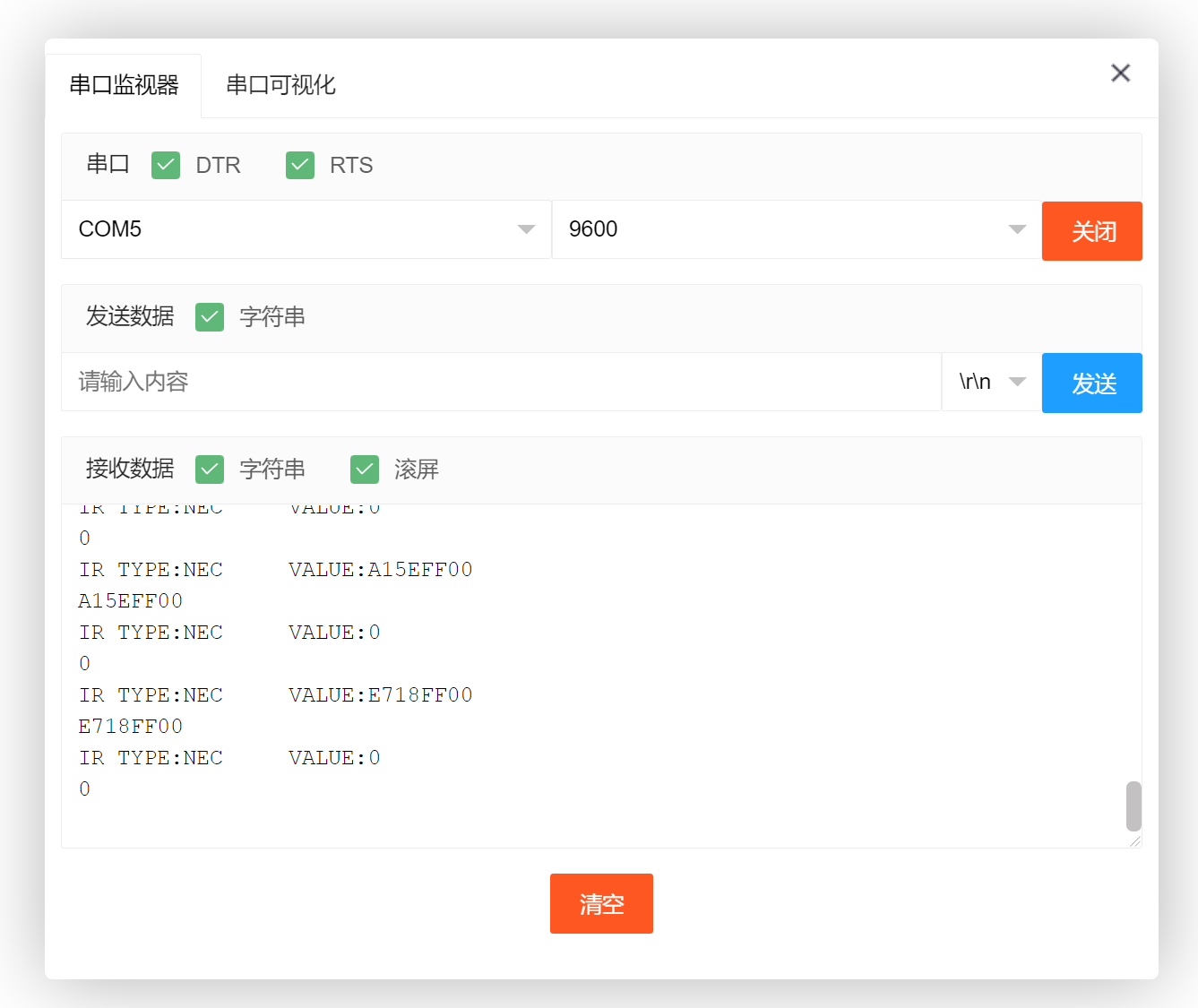
Serial.print("IR TYPE:" + irProtocol + "\tVALUE:");
Serial.println(ir_item, HEX);
irrecv_4.resume();
Serial.println(ir_item,HEX);
switch (ir_item) {
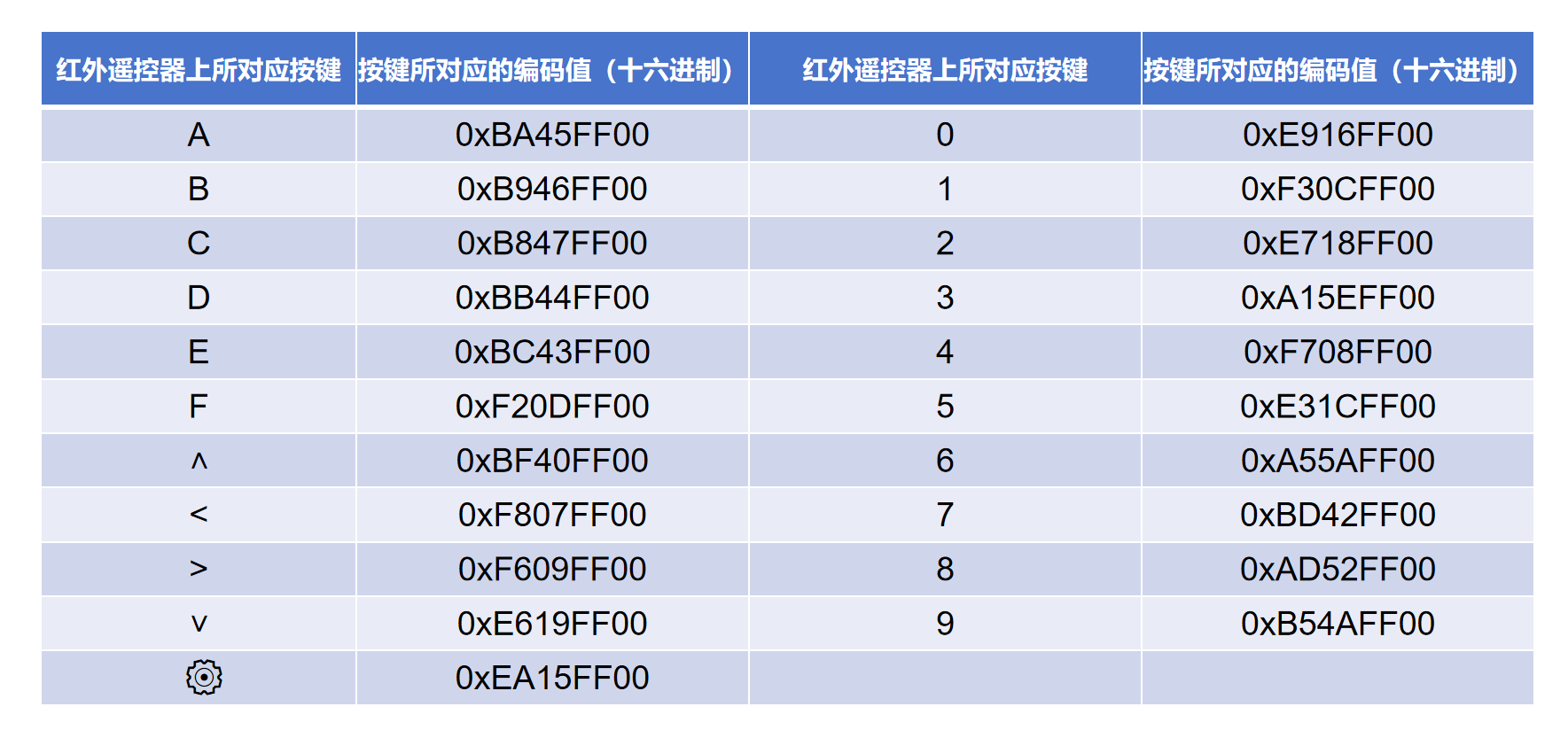
case 0xF30CFF00:
//按下遥控器“1”键编码值:F30CFF00。红灯亮。
pinMode(red, OUTPUT);
digitalWrite(red,HIGH);
pinMode(yellow, OUTPUT);
digitalWrite(yellow,LOW);
pinMode(green, OUTPUT);
digitalWrite(green,LOW);
break;
case 0xE718FF00:
//按下遥控器“2”键编码值:E718FF00。黄灯亮。
pinMode(yellow, OUTPUT);
digitalWrite(yellow,HIGH);
pinMode(red, OUTPUT);
digitalWrite(red,LOW);
pinMode(green, OUTPUT);
digitalWrite(green,LOW);
break;
case 0xA15EFF00:
//按下遥控器“3”键编码值:A15EFF00。绿灯亮。
pinMode(green, OUTPUT);
digitalWrite(green,HIGH);
pinMode(red, OUTPUT);
digitalWrite(red,LOW);
pinMode(yellow, OUTPUT);
digitalWrite(yellow,LOW);
break;
case 0xBA45FF00:
//按下遥控器“A”键编码值:BA45FF00。所以灯熄灭。
pinMode(red, OUTPUT);
digitalWrite(red,LOW);
pinMode(yellow, OUTPUT);
digitalWrite(yellow,LOW);
pinMode(green, OUTPUT);
digitalWrite(green,LOW);
break;
default:
break;
}
} else {
}
}Example Program (ESP32 Development Board — Based on Python language, cannot be uploaded using Arduino IDE):
6, Miciqi Mixly Example Program (Graphical Language)
Example Program (UNO Development Board):Click to download
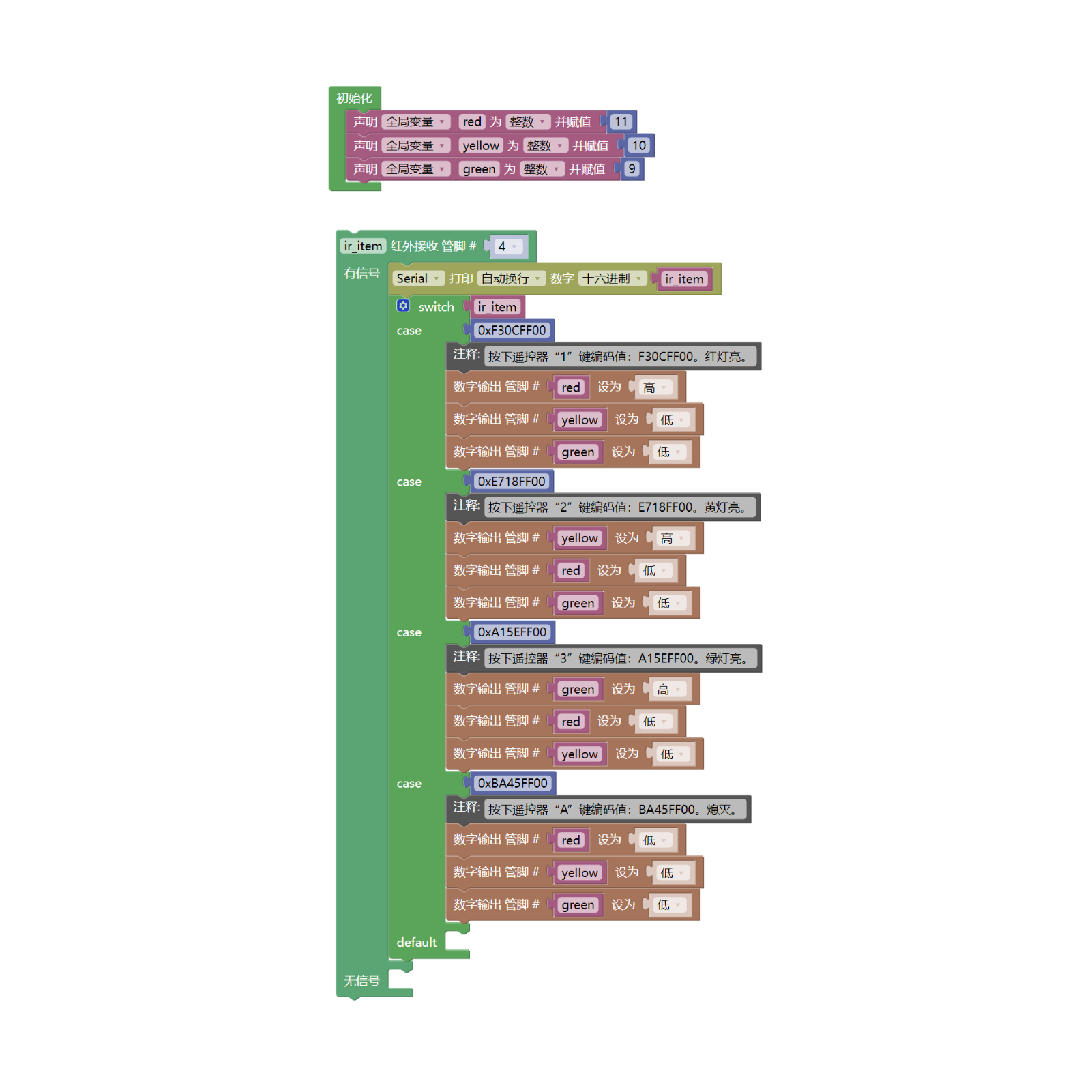
Example Program (ESP32 Development Board): Click to download
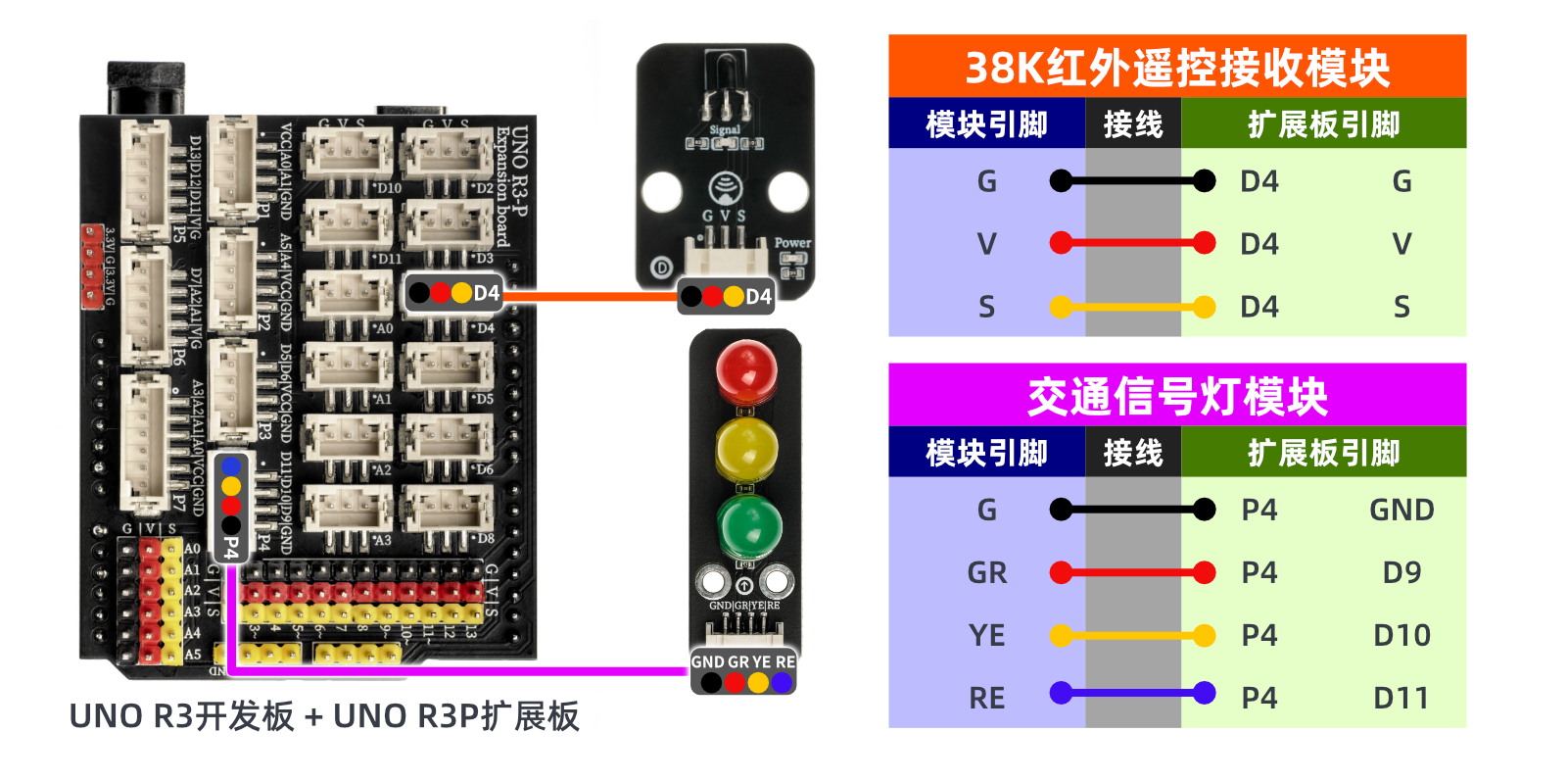
7, Test Environment Setup
Arduino UNO Test Environment Setup
Prepare Components:
HELLO STEM UNO R3 DEVELOPMENT BOARD *1
HELLO STEM UNO R3 P EXPANSION BOARD *1
Traffic Signal Module (HS-F05L) *1
38K Infrared Receiver Module (HS-S23L) *1
PH2.0 4P Double Head Terminal Line *1
PH2.0 3P dual headed terminal line *1
Infrared remote control*1
Circuit wiring diagram:
Set up Micropython environment
Prepare Components:
Circuit wiring diagram:
8. Video tutorial
Video tutorial:Click to view
9. Test conclusion