
1. Introduction
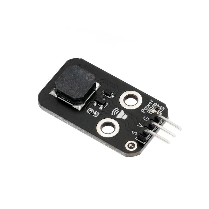
A passive buzzer is a buzzer without an internal oscillator, the internal oscillator will not emit a buzzing sound when powered on, it requires a 2~5 kHz square wave drive, and then different frequency waveforms will drive the buzzer to emit sounds at the corresponding frequency.We often see greeting cards that come with a music box, which plays birthday songs, Christmas carols, and other tunes when opened, and it is realized through a passive buzzer.
Difference between Active and Passive Buzzers:
1, active buzzer, internally has oscillation and drive circuit.Turn on the power and it will ring.A passive buzzer with controllable sound frequency, capable of producing the effect of 'Do Re Mi Fa Sol La Si'. In some special cases, it can share a control port with an LED.
2, Test the sound difference by connecting the black probe to the "+" pin of the buzzer, and the red probe to the other pin to touch back and forth. If a click, click sound is emitted and the resistance is only 8Ω, it is an inactive buzzer; if it can produce a continuous sound and the resistance is several hundred ohms or more, it is an active buzzer.
3, The vibration frequency is different, use DC voltage to input the corresponding voltage (can be adjusted from small to large), the frequency is about 2.7KHZ, and it can sound directly as an active electromagnetic buzzer. For those that do not sound directly, they need a square wave to drive in order to sound as a passive electromagnetic buzzer.
2. Schematic
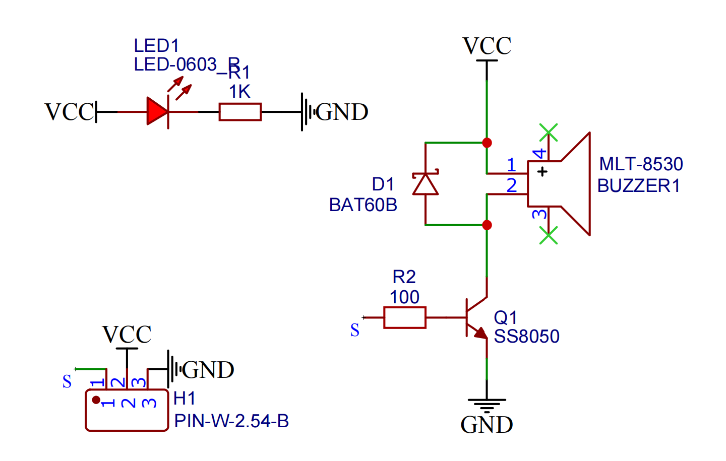
Module Parameters
Pin Name | description |
|---|---|
G | GND (Negative Power Input) |
V | VCC (Positive Power Input) |
S | Digital Signal Pin |
Power Supply Voltage: 3.3V / 5V
Connection Type: 2.54mm Header
Installation Method: Double Screw Fixed
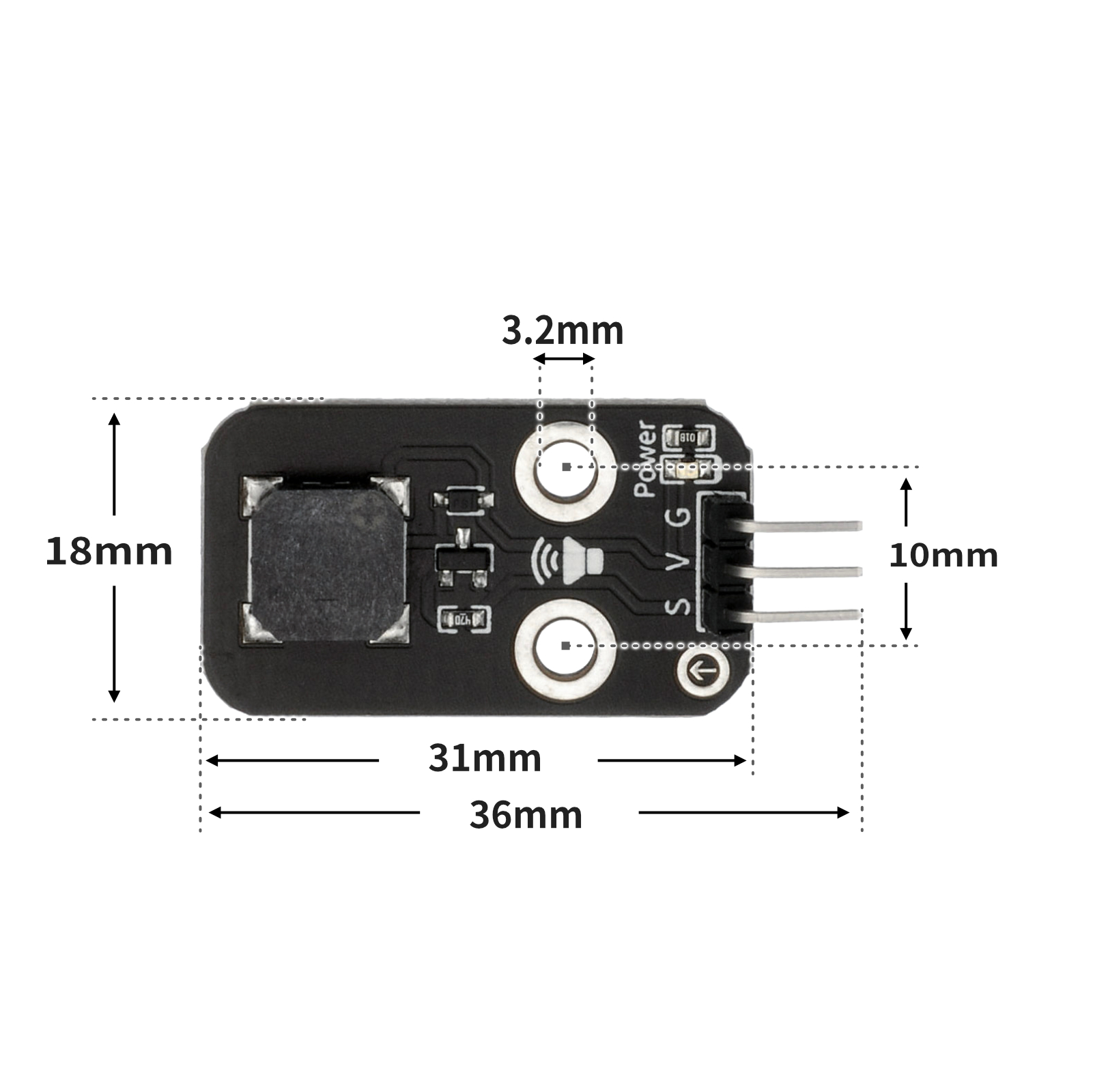
4, Circuit Board Size
5 of Arduino IDE example program
Attention: If prompted with an error message about the library file during program upload, please import the library file first!
Arduino IDE Library Download and Import Tutorial:Click to view
Example program (UNO development board):
float tonelist[7]={1046.5,1174.7,1318.5,1396.9,1568,1760,1975.5};

void setup(){
  pinMode(3, OUTPUT);
}

void loop(){
  //蜂鸣器:D3,\n播放简谱1,2,3,4,5,6

  for (int i = 1; i <= 7; i = i + (1)) {
    tone(3,tonelist[(int)(i - 1)]);
    delay(600);
    noTone(3);
    delay(600);
  }

}
6, ESP32 Python Example (for Mixly IDE/Misashi)
Choose the development board Python ESP32 [ESP32 Generic(4MB)] and upload in code mode
Attention: If prompted with an error message about the library file during program upload, please import the library file first!
Download and import tutorial for Mixly IDE ESP32 library:Click to view
Example program (ESP32-Python):
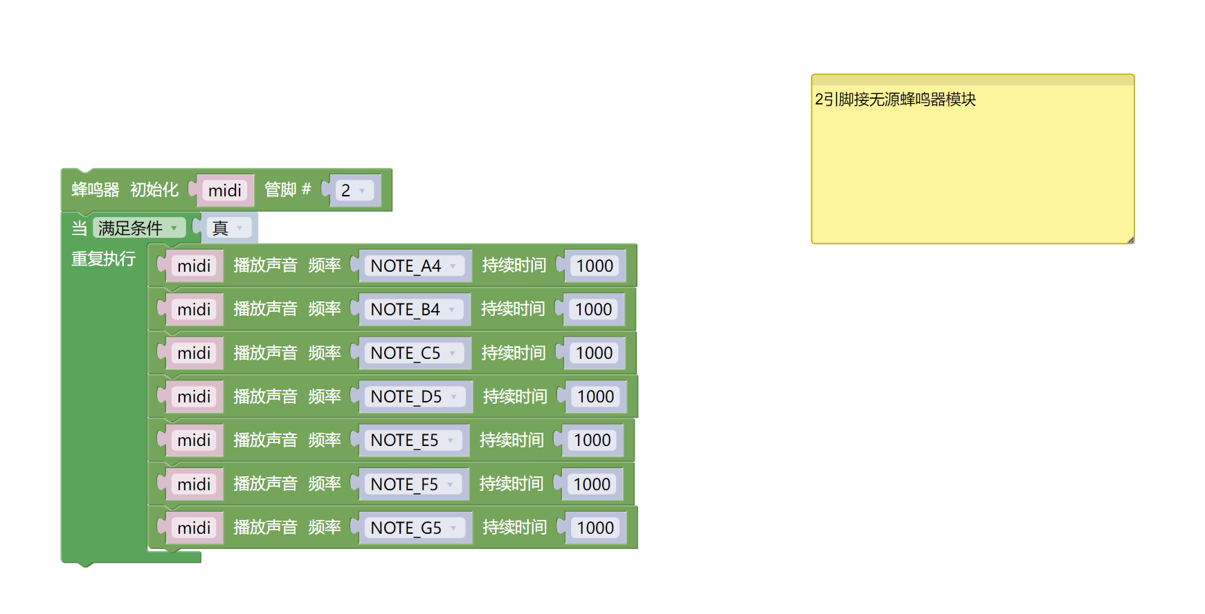
import music
midi = music.MIDI(2)
while True:
midi.pitch_time(440, 1000)
midi.pitch_time(494, 1000)
midi.pitch_time(523, 1000)
midi.pitch_time(587, 1000)
midi.pitch_time(659, 1000)
midi.pitch_time(698, 1000)
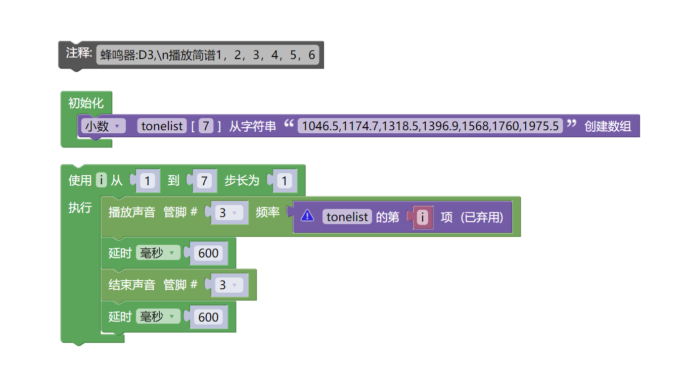
midi.pitch_time(784, 1000)7, Mixly example program (graphical language)
Example program (UNO development board):Click to download
Attention: If prompted with an error message about the library file during program upload, please import the library file first!
Download and import tutorial of Mixly IDE Arduino library:Click to view
Example Program (ESP32 Development Board):Click to download
Attention: If prompted with an error message about the library file during program upload, please import the library file first!
Download and import tutorial for Mixly IDE ESP32 library:Click to view
8. Setting up the Test Environment
Arduino UNO Test Environment Setup
Prepare Components:
HELLO STEM UNO R3 PRO DEVELOPMENT BOARD *1
USB TYPE-C DATA CABLE *1
Passive buzzer module (HS-F02A) *1
1P female to female DuPont wire *3 pieces or 3P female to female DuPont wire *1 piece
Circuit wiring diagram:
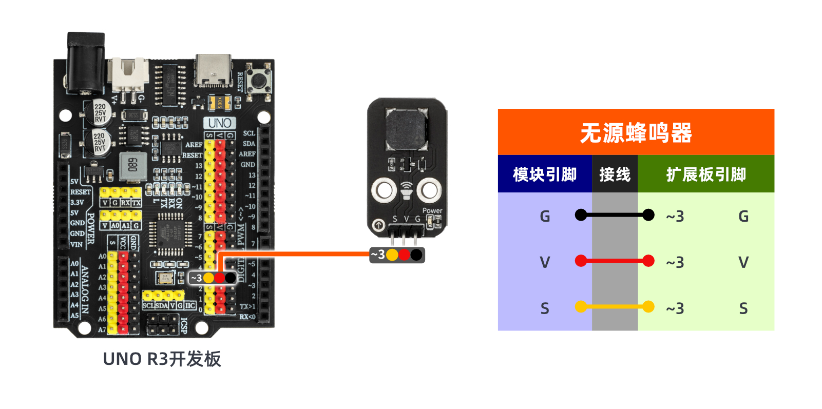
ESP32 Test Environment Setup
Prepare Components:Pending update...
Circuit wiring diagram:Pending update...
9, Video tutorial
Video tutorial:Click to view
10, Test results
Arduino UNO test results:
After connecting the device lines, after burning the above program to the Arduino UNO development board, you will hear the buzzer emit different frequencies of sound.