
1. Introduction
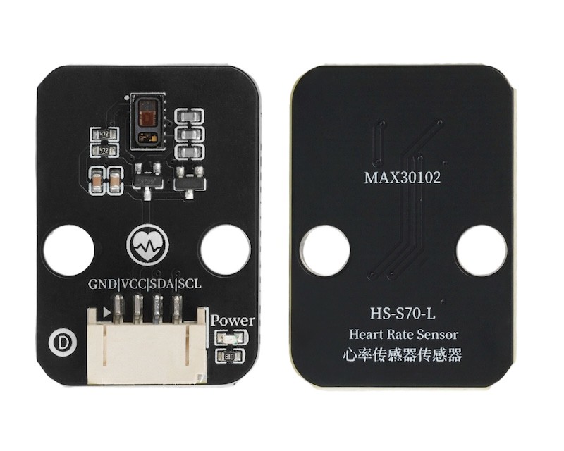
The heart rate sensor is an electronic device used to monitor the frequency and rhythm of heartbeats, widely used in fields such as healthcare, sports fitness, and smart wearables.
2. Schematic
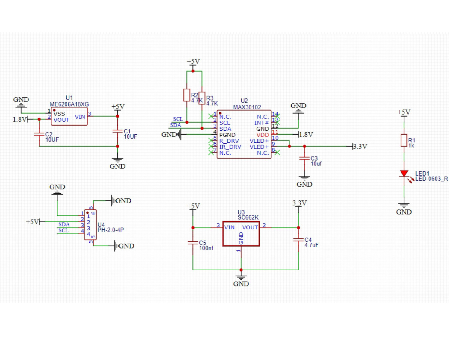
Module Parameters
Pin Name | description |
|---|---|
GND | GND (Negative Power Input) |
VCC | VCC (Positive Power Input) |
A | IIC Data Transmission Pin |
L | I2C communication clock pin |
Power supply voltage: 3.3V - 5V
Connection method: PH2.0 4P terminal wire
Installation method: Brick installation
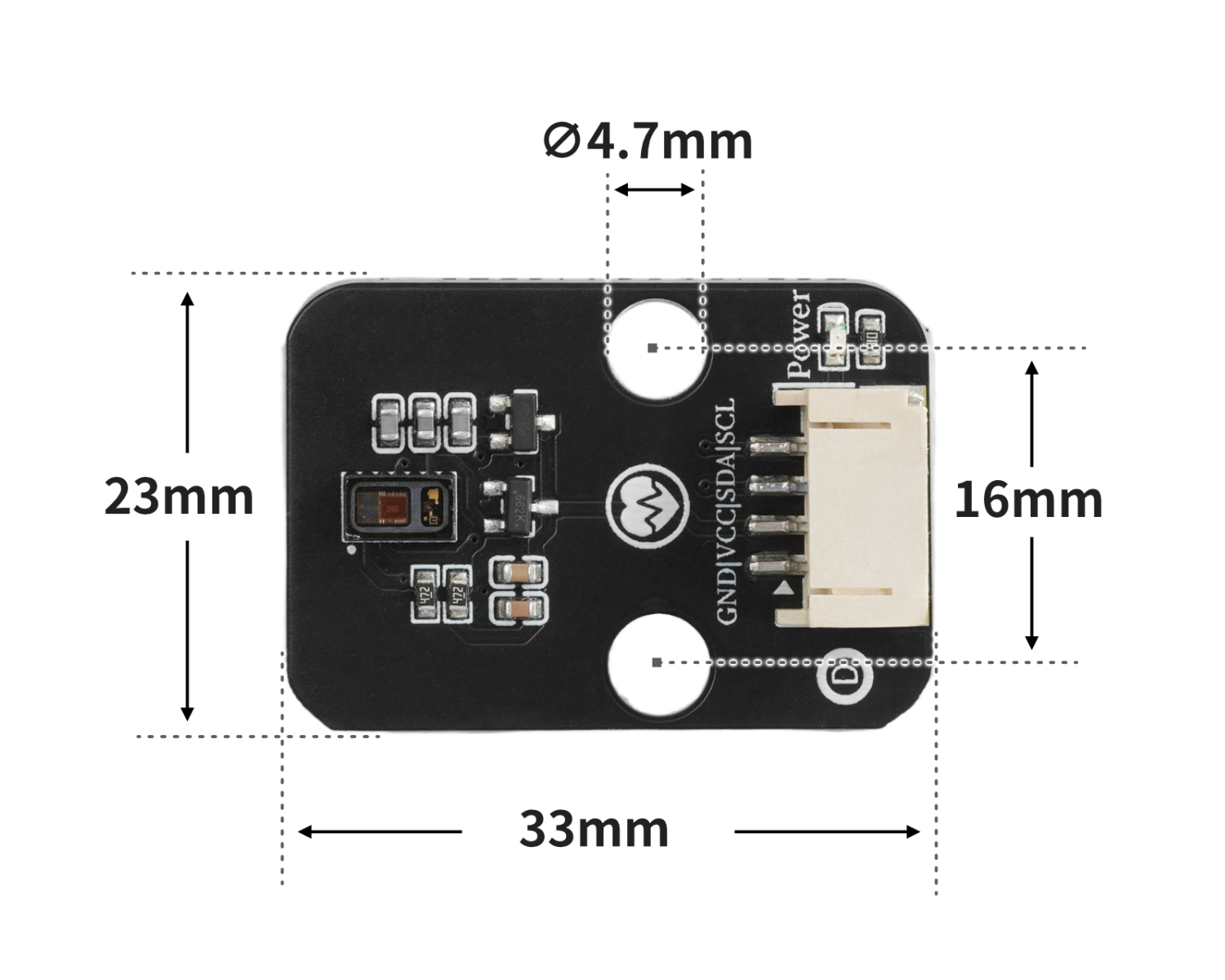
4, Circuit Board Size
5 of Arduino IDE example program
Example program (UNO development board): Click to download
#include <Wire.h>
#include "MAX30105.h"
#include "heartRate.h"

MAX30105 particleSensor;
const byte RATE_SIZE = 4; //Increase this for more averaging. 4 is good.
 byte rates[RATE_SIZE]; //Array of heart rates
 byte rateSpot = 0;
 long lastBeat = 0; //Time at which the last beat occurred
 float beatsPerMinute;
 int Bpm_value;

void setup(){
  Serial.begin(9600);
  particleSensor.begin(Wire, I2C_SPEED_FAST);
  particleSensor.setup(); //Configure sensor with default settings
  particleSensor.setPulseAmplitudeRed(0x0A); //Turn Red LED to low to indicate sensor is running
  particleSensor.setPulseAmplitudeGreen(0); //Turn off Green LED

}

void loop(){
  long irValue = particleSensor.getIR();
  if (checkForBeat(irValue) == true)
    {
      //We sensed a beat!
      long delta = millis() - lastBeat;
      lastBeat = millis();
      beatsPerMinute = 60 / (delta / 1000.0);
      if (beatsPerMinute < 255 && beatsPerMinute > 20)
      {
        rates[rateSpot++] = (byte)beatsPerMinute; //Store this reading in the array
        rateSpot %= RATE_SIZE; //Wrap variable
        //Take average of readings
  Bpm_value = 0;
        for (byte x = 0 ; x < RATE_SIZE ; x++)
  Bpm_value += rates[x];
  Bpm_value /= RATE_SIZE;
      }
    }
    Serial.print("Bpm_value = ");
    Serial.print(Bpm_value);
    Serial.println(" bpm");

}
Example Program (ESP32 Development Board — Based on Python language, cannot be uploaded using Arduino IDE):
from machine import I2C, Pin
import time

MAX3010X_I2C_ADDR = 0x57
REG_FIFOWRITEPTR   = 0x04
REG_FIFOOVERFLOW   = 0x05
REG_FIFOREADPTR    = 0x06
REG_FIFODATA       = 0x07
REG_FIFOCONFIG     = 0x08
REG_MODECONFIG     = 0x09
REG_PARTICLECONFIG = 0x0A
REG_LED1_PA        = 0x0C
REG_LED2_PA        = 0x0D
REG_MULTILEDCONFIG1= 0x11
REG_MULTILEDCONFIG2= 0x12
REG_PARTID         = 0xFF
EXPECTED_PARTID    = 0x15

def _mask_write(i2c, addr, reg, mask, bits):
    cur = i2c.readfrom_mem(addr, reg, 1)[0]
    cur &= mask
    cur |= bits
    i2c.writeto_mem(addr, reg, bytes([cur]))

class MAX3010x:
    def __init__(self, i2c, address=MAX3010X_I2C_ADDR):
        self.i2c = i2c
        self.address = address

    def read_reg(self, reg):
        return self.i2c.readfrom_mem(self.address, reg, 1)[0]

    def write_reg(self, reg, val):
        self.i2c.writeto_mem(self.address, reg, bytes([val & 0xFF]))

    def soft_reset(self):
        _mask_write(self.i2c, self.address, REG_MODECONFIG, 0xBF, 0x40)
        t0 = time.ticks_ms()
        while time.ticks_diff(time.ticks_ms(), t0) < 100:
            if (self.read_reg(REG_MODECONFIG) & 0x40) == 0:
                return True
            time.sleep_ms(1)
        return False

    def setup(self):
        self.soft_reset()
        _mask_write(self.i2c, self.address, REG_FIFOCONFIG, 0b11100000, 0x40)
        _mask_write(self.i2c, self.address, REG_FIFOCONFIG, 0xEF, 0x10)
        _mask_write(self.i2c, self.address, REG_MODECONFIG, 0xF8, 0x03)
        _mask_write(self.i2c, self.address, REG_PARTICLECONFIG, 0x9F, 0x60)
        _mask_write(self.i2c, self.address, REG_PARTICLECONFIG, 0xE3, 0x00)
        _mask_write(self.i2c, self.address, REG_PARTICLECONFIG, 0xFC, 0x03)
        self.write_reg(REG_LED1_PA, 0x4F)
        self.write_reg(REG_LED2_PA, 0x4F)
        _mask_write(self.i2c, self.address, REG_MULTILEDCONFIG1, 0xF8, 0x01)
        _mask_write(self.i2c, self.address, REG_MULTILEDCONFIG1, 0x8F, 0x20)
        self.write_reg(REG_FIFOREADPTR, 0)
        self.write_reg(REG_FIFOOVERFLOW, 0)
        self.write_reg(REG_FIFOWRITEPTR, 0)

    def read_fifo_red_ir(self):
        if self.read_reg(REG_FIFOREADPTR) == self.read_reg(REG_FIFOWRITEPTR):
            return None
        data = self.i2c.readfrom_mem(self.address, REG_FIFODATA, 6)
        red = ((data[0] << 16) | (data[1] << 8) | data[2]) & 0x3FFFF
        ir  = ((data[3] << 16) | (data[4] << 8) | data[5]) & 0x3FFFF
        return red, ir

lastBeatTime = 0
threshold = 2000
peak = 0
trough = 999999
amp = 0
IBI = 600
firstBeat = True
secondBeat = False
rate = [600] * 10
rate_index = 0

def checkForBeat(ir_value):
    global threshold, peak, trough, amp
    global lastBeatTime, firstBeat, secondBeat
    global IBI, rate, rate_index
    now = time.ticks_ms()
    signal = ir_value
    if signal < threshold and signal < trough:
        trough = signal
    if signal > threshold and signal > peak:
        peak = signal
    if signal > threshold and (time.ticks_diff(now, lastBeatTime) > 300):
        IBI = time.ticks_diff(now, lastBeatTime)
        lastBeatTime = now
        if firstBeat:
            firstBeat = False
            secondBeat = True
            return False
        if secondBeat:
            secondBeat = False
            for i in range(len(rate)):
                rate[i] = IBI
        rate[rate_index] = IBI
        rate_index = (rate_index + 1) % len(rate)
        amp = peak - trough
        threshold = trough + amp * 0.5
        peak = threshold
        trough = threshold
        return True
    if time.ticks_diff(now, lastBeatTime) > 2500:
        threshold = signal * 0.97
        peak = threshold
        trough = threshold
        firstBeat = True
        secondBeat = False
    return False

def read_bpm(timeout_ms=8000):
    i2c = I2C(1, scl=Pin(22), sda=Pin(21), freq=400000)
    sensor = MAX3010x(i2c)
    sensor.setup()
    start = time.ticks_ms()
    while time.ticks_diff(time.ticks_ms(), start) < timeout_ms:
        data = sensor.read_fifo_red_ir()
        if not data:
            time.sleep_ms(5)
            continue
        red, ir = data
        if ir < 20000:
            continue
        if checkForBeat(ir):
            avg_IBI = sum(rate) / len(rate)
            bpm = 60000 / avg_IBI
            new_bpm = bpm - 80
            if new_bpm < 0:
                return 0
            else:
                return int(new_bpm)
    return 0

import machine


while True:
    xinlv = read_bpm()
    print(('心率值(BMP):' + str(xinlv)))
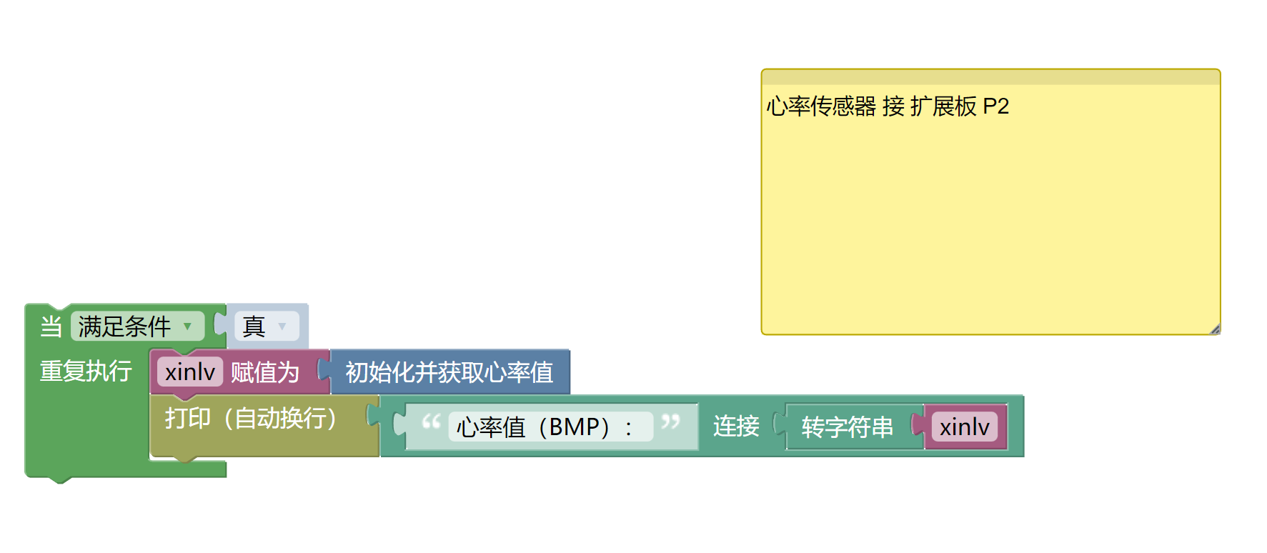
6, Miciqi Mixly Example Program (Graphical Language)
Example program (UNO development board):Click to download
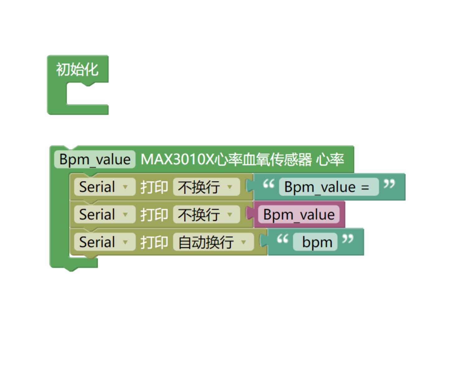
Example Program (ESP32 Development Board):Click to download
7, Test Environment Setup
Setting up the Arduino Environment
Prepare Components:
HELLO STEM UNO R3 DEVELOPMENT BOARD *1
HELLO STEM UNO EXP1 Expansion Board *1
USB TYPE-C DATA CABLE *1
Heart rate sensor module (HS-S70-L)*1
PH2.0 4P terminal line *1
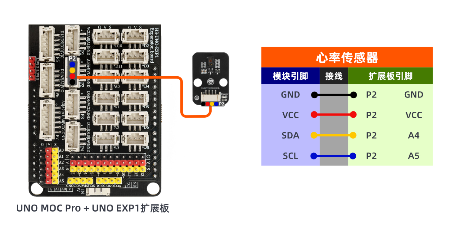
Circuit wiring diagram:
Set up Micropython environment
Prepare Components:
ESP32EA MOC development board *1
ESP32-EXP1 Expansion Board *1
USB TYPE-C DATA CABLE *1
Heart rate sensor module (HS-S70-L)*1
PH2.0 4P terminal line *1
Circuit wiring diagram:
8, Add Arduino library file
Reference here if you don't know how to use library files:Install and use library files
Library file:Click to download
Installation steps for the MiQi UNO development board library (download and install the MiQi library before using the code):Reference link
9, Add MicroPython environment library
MiXin ESP32 development board library download and installation steps (download and install the MiXin library before using the code):Reference link
10, video tutorial
Video tutorial: Click to view
11. Test Conclusion
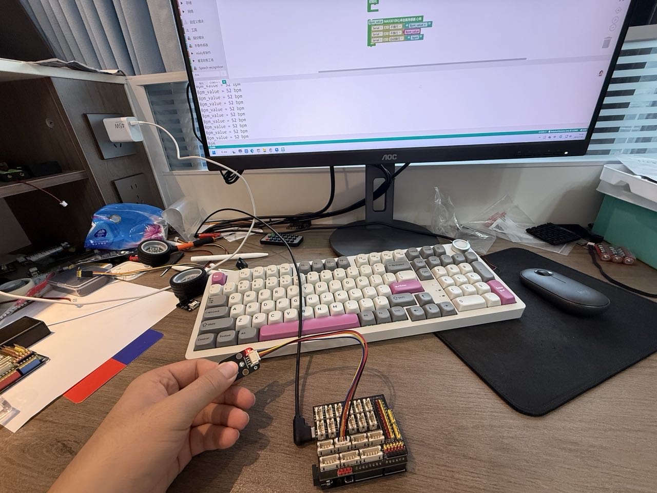
After the device is connected to the wire, upload the above program to the development board, and you can then see the heart rate sensor module data test.