
1. Introduction
2, Technical Specifications
Microcontroller | ATmega328P-PU |
|---|---|
Operating Voltage | 5V |
Input Voltage (Recommended) | 6-9V (DC Direct Current) |
Digital Pin | 14 units (6 of which provide PWM output) |
PWM digital I/O pin | 6 (D3, D5, D6, D9, D10, D11) |
Analog Input Pin | 6 (A0-A5) |
Direct current (S) for each I/O pin | 20 milliamperes (mA) |
5V Direct Current Power Output (G|V) | 2000mAh |
Flash Memory | 32 KB (ATmega328), of which 0.5 KB is used by the bootloader |
SRAM | 2 KB (ATmega328P-PU) |
EEPROM | 1 KB (ATmega328P-PU) |
Clock Frequency | 16 MHz |
On-board LED | D13 |
3, Features
1. Compatible with Lego programming brick mounting holes, can be installed directly on Lego bricks
2, Enhance power supply, G|V can provide a maximum output of 5V2.5A/3.3V1A
3, Onboard circuit protection and power selection circuit
4, Type-C communication interface, supports A2C/C2C cables, no need to distinguish between positive and negative, more convenient
5, supports PH2.0-4P and XH2.54 socket types for two kinds of input interfaces, allowing 6-9VDC input
6, on-board 2.54mm pitch G|V|S expansion pin interface, without expansion board usage
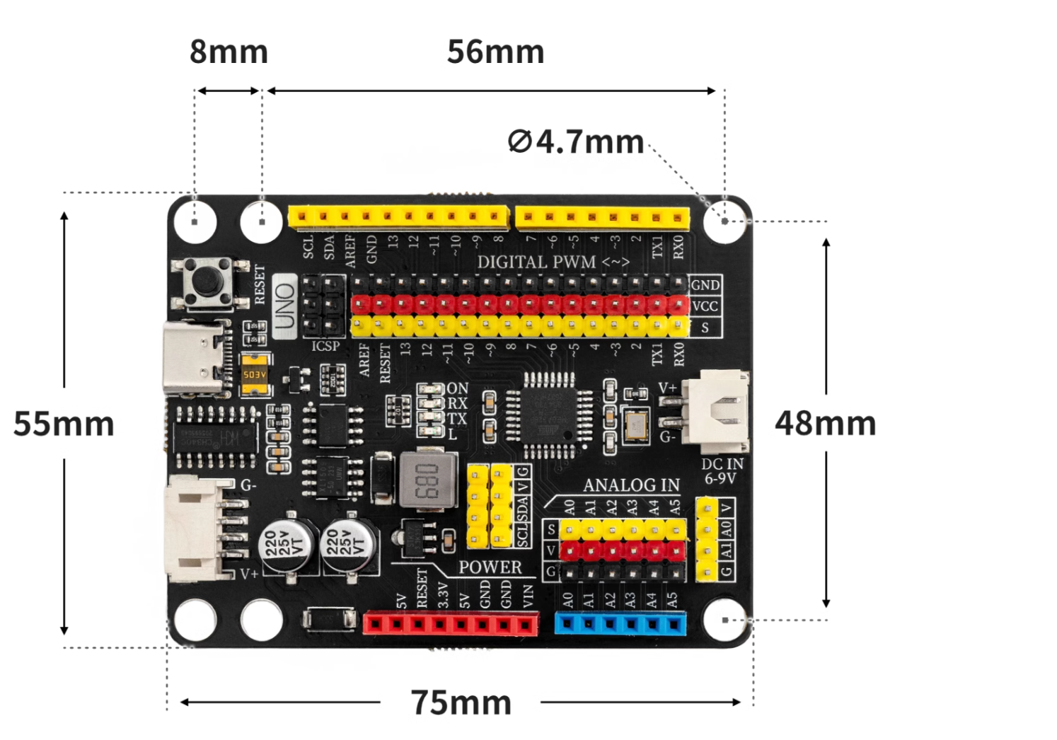
4, Circuit Board Size
5, Development board decoding
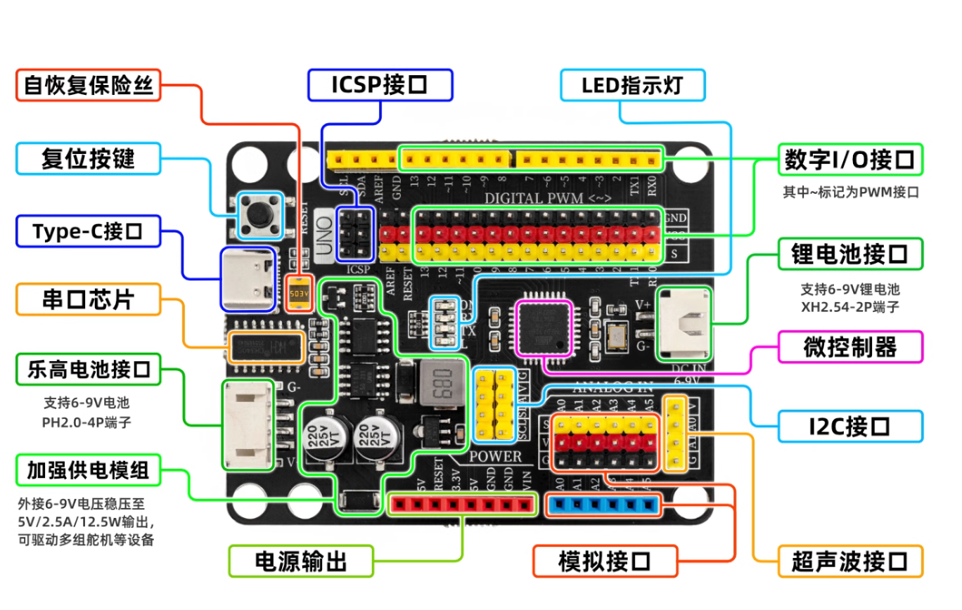
①Reset key
Press the reset button and run the program again.②USB serial chip
This chip is responsible for converting the data received from USB into serial data for the main control chip.③DC power interface and reinforced power supply module
The power module is responsible for the power supply service of the motherboard, the 6-12V power supply from the external access is stepped down to 5V/2A/10W output, and can drive multiple servos, toy motors, miniature slides and other devices.④Self-recovery fuse
When the development board is connected incorrectly, causing a short circuit, the fuse will automatically disconnect the circuit connection between the development board and the computer, thereby protecting the computer USB port from being burnt or the computer from crashing.⑤Type-C interface
responsible for data download and USB power supply.⑥Power switching chip
FDN340P field effect transistor + LMV358IDGKR amplifier composed of external power supply and USB power supply automatic switching control system.The development board is powered by USB interface by default. When an external power source is connected, the controller will automatically disconnect the USB power and switch to external power supply. After the external power source is disconnected, it will automatically switch back to USB power supply. This feature can protect the computer from the power interference of the development board's external power supply.⑦Microcontroller
The ATMEGA328P microcontroller is the brain of the development board, responsible for program storage, execution, calculation processing, signal input and output, and other functions.⑧Serial port chip
This chip operates when writing initialization program to the development board or using the compiler to download the program.⑨ICSP serial data interface
Connect this interface when writing the initialization program to the development board or using the compiler to download the program.⑩LED indicator light
The board is equipped with 4 LED indicators, (ON) is the power indicator, it lights up when powered on, (RX)(TX) are serial port signal indicators, the LED lights blink when there is serial port communication, (L) is the D13 pin indicator light, the light is on when the D13 signal is high.
Notice
UNO-MOC-PRO has a resettable multi-fuse, which can protect the computer's USB port from short-circuit and overcurrent damage.If a current greater than 500 mA is applied to the USB port, the fuse will automatically disconnect until the short circuit or overload is removed.