1. Introduction
The DS1307 clock module is a low-power, full BCD code clock calendar real-time clock chip with 56 bytes of non-volatile RAM, the address and data are transmitted through a two-wire bidirectional serial bus, the chip can provide seconds, minutes, hours and other information, and the number of days in each month can be automatically adjusted.The AM/PM flag determines whether the clock operates in 24-hour or 12-hour mode, the chip has an integrated power sensing circuit with power failure detection and battery switching function.The DS1307 clock module is a sensor integrated with a digital clock, allowing users to write their own programs to create an electronic clock.
2. Schematic
Clock Module-HS-S30A SchematicClick to view
Module Parameters
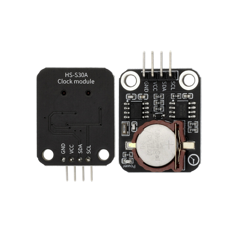
Pin Name | description |
|---|---|
GND | GND (Negative Power Input) |
VCC | VCC (Positive Power Input) |
SDA | Serial Data Pin |
SCL | Serial Clock Pin |
Power Supply Voltage: 3.3V / 5V
Connection Type: 2.54mm Header
Installation method: Screw fixed
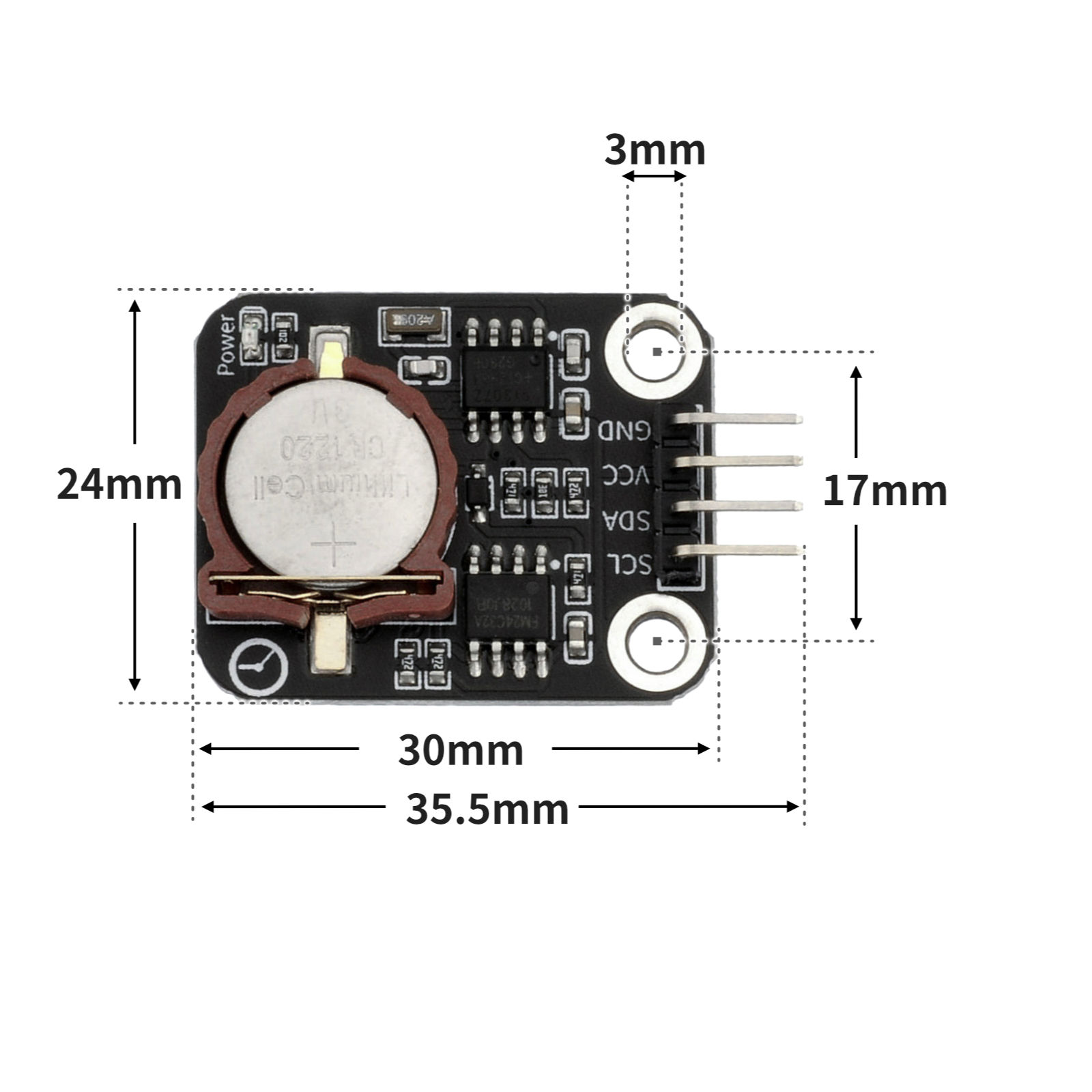
4, Circuit Board Size
5 of Arduino IDE example program
Attention: If prompted with an error message about the library file during program upload, please import the library file first!
Arduino IDE Library Download and Import Tutorial:Click to view
Example program (UNO development board):
#include <RtcDS1307.h>
#include <Wire.h>

RtcDS1307<TwoWire> Rtc(Wire);

void setup(){
  Serial.begin(9600);
  Rtc.Begin();
  Rtc.SetIsRunning(true);
  Rtc.SetDateTime(RtcDateTime(__DATE__, __TIME__));
}

void loop(){
  //DS1307时钟模块接开发板llc(A4,A5)

  Serial.print(String(String("Date") + String(":")) + String(String(Rtc.GetDateTime().Year()) + String("-")) + String(String(Rtc.GetDateTime().Month()) + String("-")) + String(String(Rtc.GetDateTime().Day()) + String("-")));
  Serial.println(String(String("Time") + String(":")) + String(String(Rtc.GetDateTime().Hour()) + String("-")) + String(String(Rtc.GetDateTime().Minute()) + String("-")) + String(Rtc.GetDateTime().Second()));

}
6, ESP32 Python Example (for Mixly IDE/Misashi)
Choose the development board Python ESP32 [ESP32 Generic(4MB)] and upload in code mode
Attention: If prompted with an error message about the library file during program upload, please import the library file first!
Download and import tutorial for Mixly IDE ESP32 library:Click to view
Example program (ESP32-Python):
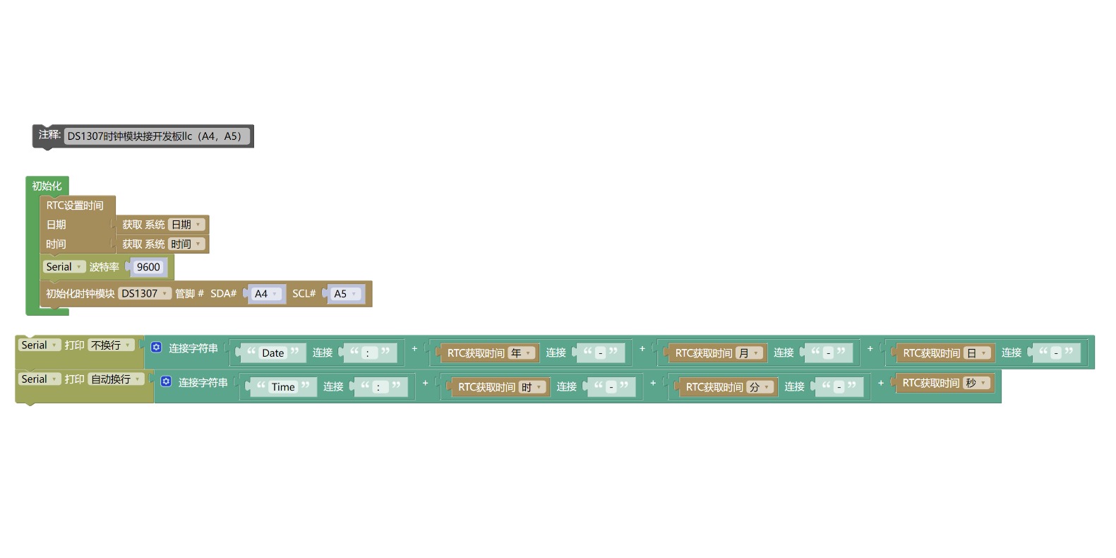
待更新...7, Mixly example program (graphical language)
Example program (UNO development board):Click to download
Attention: If prompted with an error message about the library file during program upload, please import the library file first!
Download and import tutorial of Mixly IDE Arduino library:Click to view
Example Program (ESP32 Development Board):Click to download
Attention: If prompted with an error message about the library file during program upload, please import the library file first!
Download and import tutorial for Mixly IDE ESP32 library:Click to view
Image pending update...
8. Setting up the Test Environment
Arduino UNO Test Environment Setup
Prepare Components:
HELLO STEM UNO R3 DEVELOPMENT BOARD *1
HELLO STEM UNO R3 P EXPANSION BOARD *1
USB TYPE-C DATA CABLE *1
DS1307 clock module *1
PH2.0 6P socket to Dupont wire *1 or PH2.0 6P double-ended socket wire *1
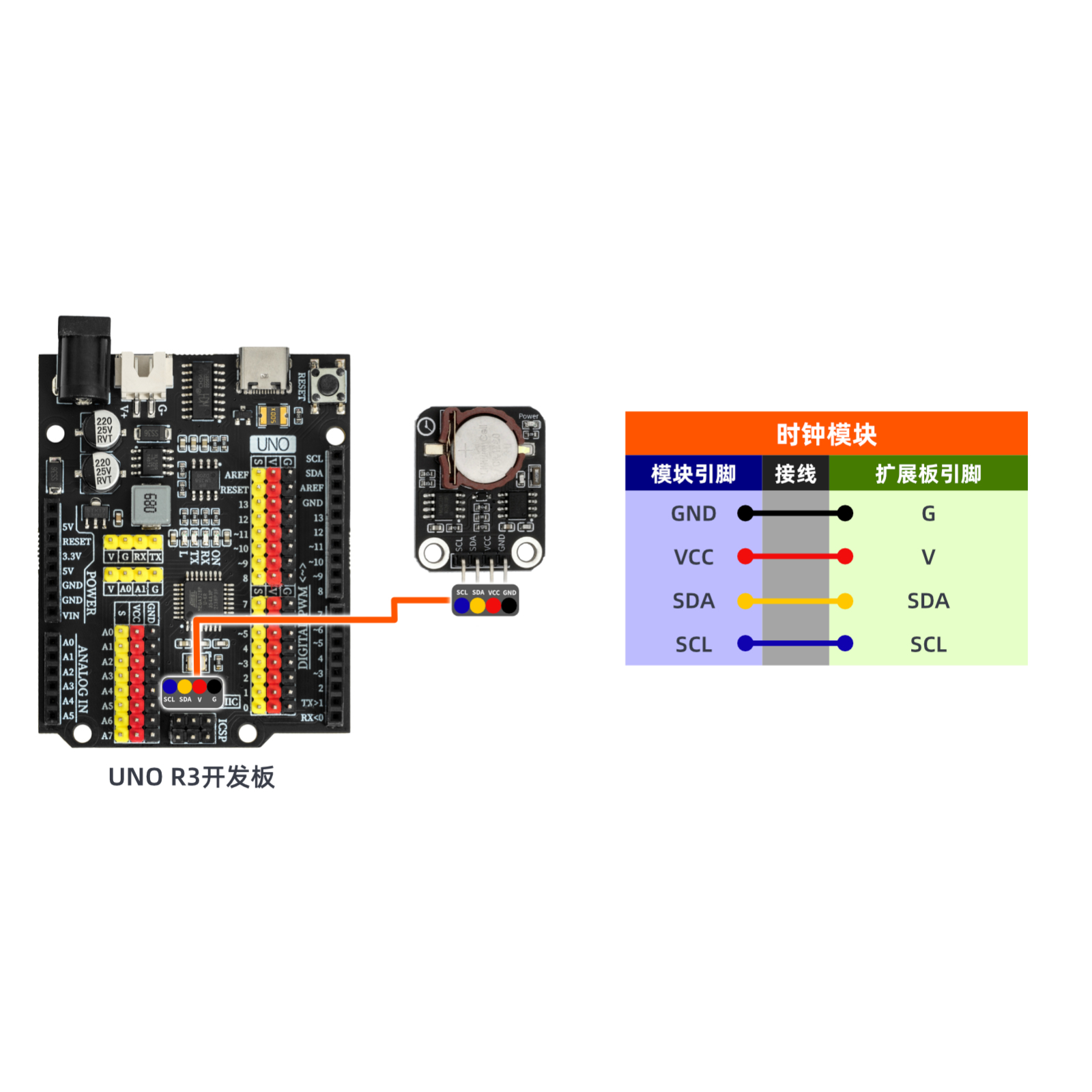
Circuit wiring diagram:
ESP32 Test Environment Setup
Prepare Components:Pending update...
Circuit wiring diagram:Pending update...
9, Video tutorial
Video tutorial:Click to view
10, Test results
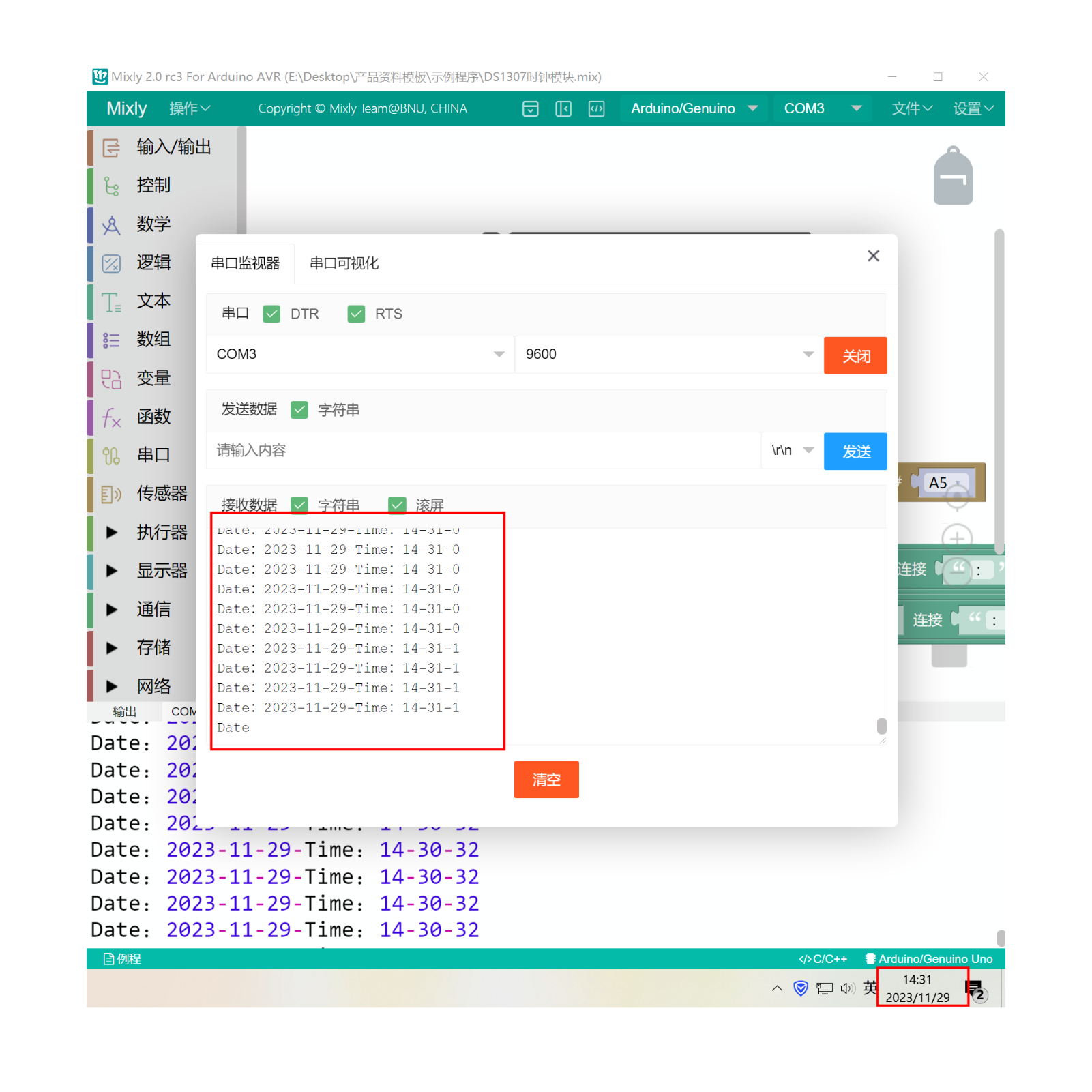
Arduino UNO test results:
After the device is connected and the above program is uploaded to the Arduino UNO development board, open the Mxily serial port monitor, and the serial port prints the date and time read by the DS1307 clock module from the system time.