
1. Introduction
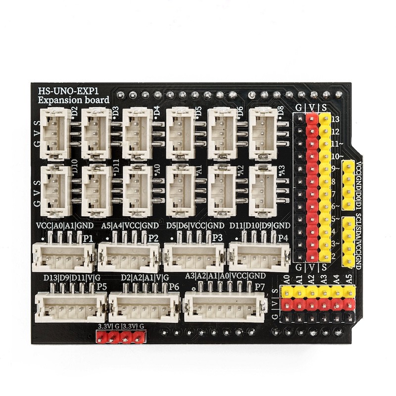
HS-UNO-EXP1 (expansion board) is a matching expansion board designed based on the Arduino Uno development board, integrating the pins of the development board onto a PCB circuit board.This expansion board is compatible with all the HELLO STEM UNO series development boards.The circuit board has a PH2.0 interface and also retains a pin header, meeting the different wiring needs of users.Can achieve wiring convenience at the same time, and also allows users to flexibly add and remove external expansion modules.
2, Characteristics
1, digital IO pins (pins from D2 to D13) and analog IO (pins from A0 to A5) pins are provided. (It can meet the need of connecting extension modules with Dupont wires.)
2, there are digital IO ports PH2.0 3P sockets (pin numbers from D2 to D11) and analog IO ports PH2.0 3P sockets (pin numbers from A0 to A3) as well as 4 PH2.0 4P sockets, 2 PH2.0 5P sockets, and 1 PH2.0 6P socket.
3, It has a 3.3V power pin that can be used for modules with small external current requirements.
3, Expansion Board Parsing
Digital IO port PH2.0 3P socket (D2-D11) and digital IO port pin header (D2-D13)
You can specify these IO ports as digital outputs, that is, output high level or low level.Among (D2 and D3 pins can be used as hardware interrupt pins.)D3,D5,D6,D9,D10,D11 pins can output analog signals).
Simulated IO port PH2.0 3P socket (A0-A3) and simulated IO port pin header (A0-A5)
You can specify these IO ports for simulated input and simulated input. The simulated input returns a value of (0-1023). The simulated output value is (0-255).
P1 socket
The socket circuit is designed for VCC/A0/A1/GND for convenient connection with some modules using PH2.0 4P interfaces (compatible modules:)HS-SR04LUltrasonic Sensor)
P2 seat
The subcircuit of this seat is designed with A5/A4/VCC/GND for easy connection with some matching modules using a PH2.0 4P interface. (Matching module:HS-S63-LTCS342 color sensor, HS-F14LTM1650 four-digit LED digital tube module, HS-F15LTM637 four-digit clock digital tube module, HS-F19LOLED display, HS-F21LLCD1602 display/)
P3 bracket
The socket circuit is designed as D5/D6/VCC/GND for convenient connection with some modules using a PH2.0 4P interface.Voice recognition control module& HS-F04LMotor drive module& HS-F20LMotor Module, HS-F10LMotor drive module, HS-S49PLMP3 Audio Broadcast Module/HS-F23-L1-digit digital tube, HS-S60-LBluetooth module)
P4 socket
The subcircuit design is for D11/D10/D9/GND for easy connection with some modules using a PH2.0 4P interface. (Adaptable module: HS-F05LTraffic Signal Module, HS-F01LRGB LED Module)
P5 Socket
This subcircuit design is for D13/D9/D11/V/G to facilitate mating with some modules using a PH2.0 5P interface. (For example, HS-F13L)8x8 dot matrix display moduleHS-F24-L1-digit digital tube)
P6 seat
The sub-circuit design is for D2/A2/A1/V/G for easy connection with some modules using the PH2.0 5P interface. (Compatible module: HS-S34L)Dual-axis joystick moduleHS-S32LRotary encoder)
P7 socket
The subcircuit is designed as A3/A2/A1/A0/V/G for convenient connection with some modules using a PH2.0 6P interface.4P button module)