
1. Introduction
2. Schematic
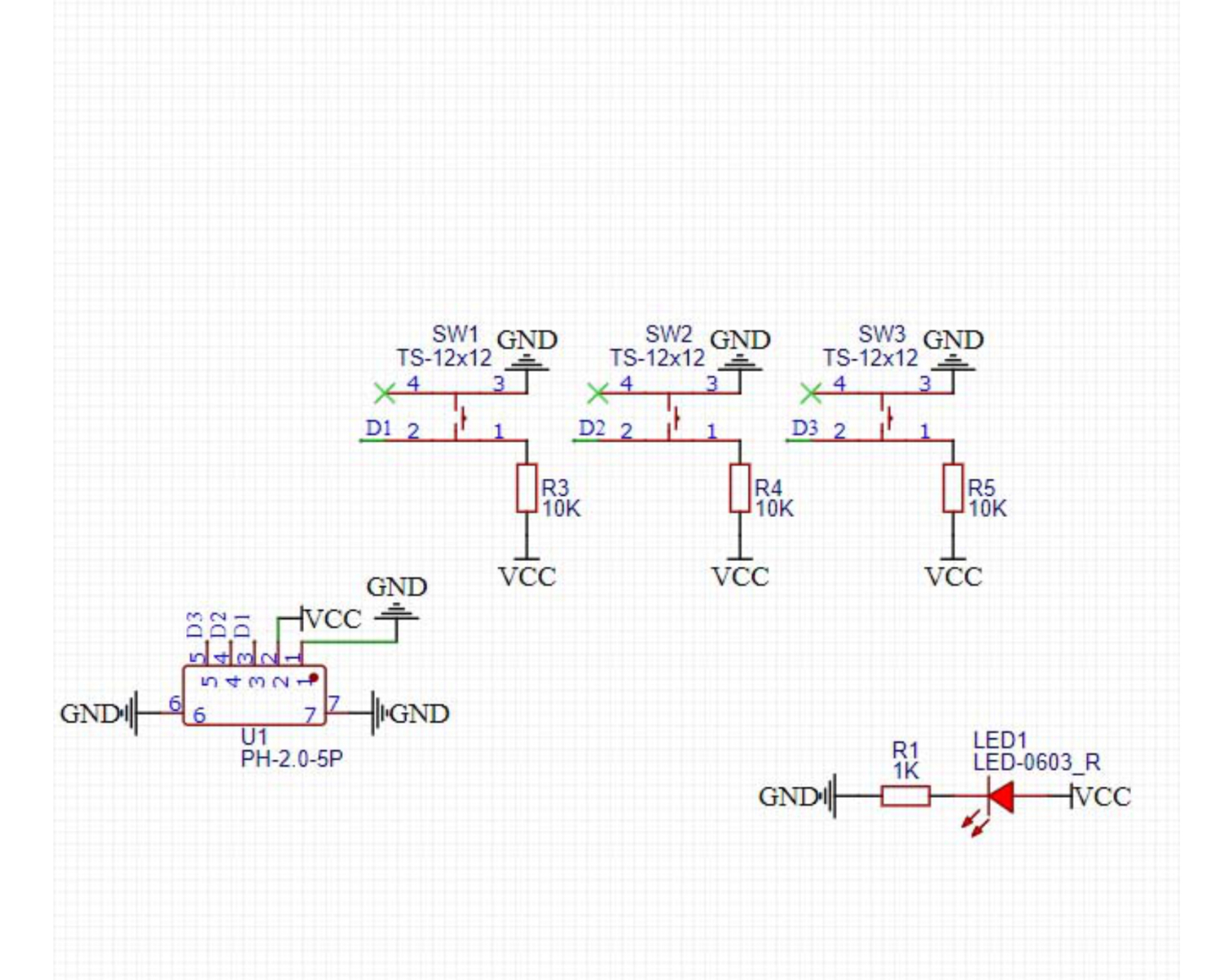
Module Parameters
Pin Name | description |
|---|---|
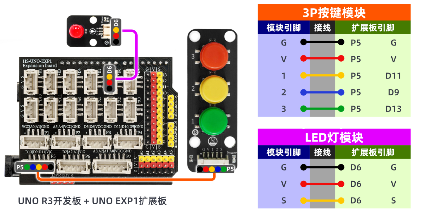
G | GND (Negative Power Input) |
V | VCC (Positive Power Input) |
1 | Digital Signal Pin |
2 | Digital Signal Pin |
3 | Digital Signal Pin |
Power Supply Voltage: 3.3V / 5V
Connection method: PH2.0 terminal wire
Installation method: Modular fixed
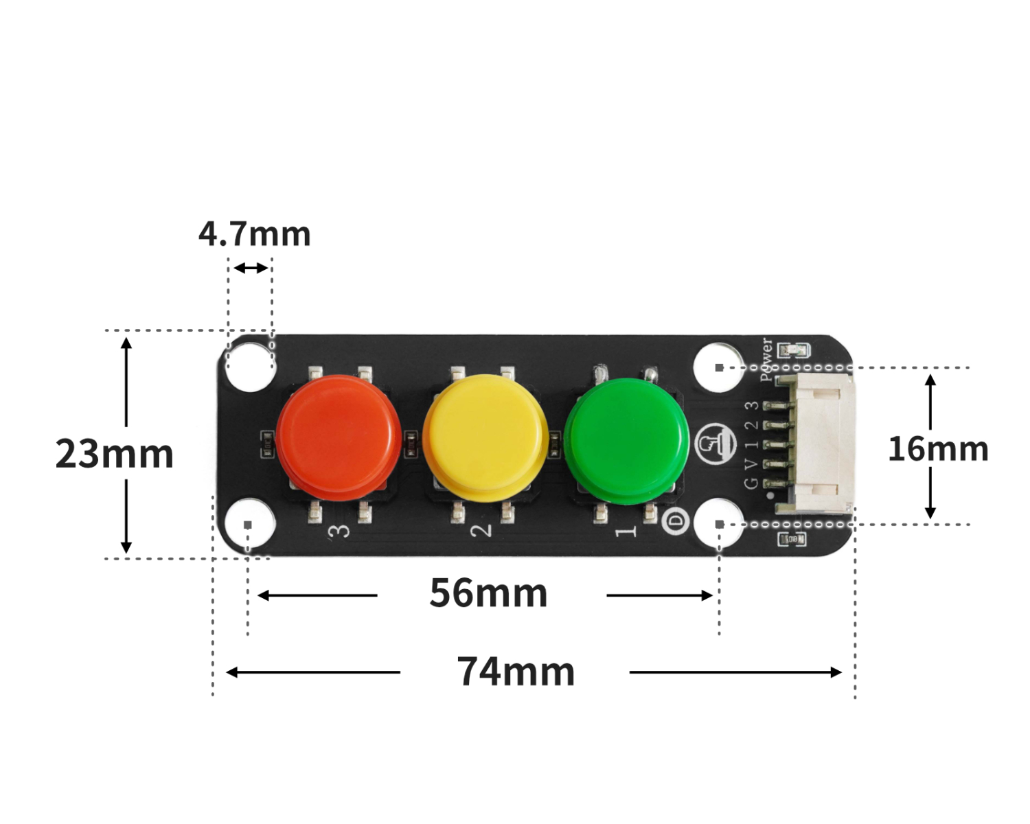
4, Circuit Board Size
5 of Arduino IDE example program
Example program (UNO development board): Click to download
volatile int light;
void setup(){
light = 0;
pinMode(6, OUTPUT);
analogWrite(6, 0);
pinMode(11, INPUT);
pinMode(9, INPUT);
pinMode(13, INPUT);
}
void loop(){
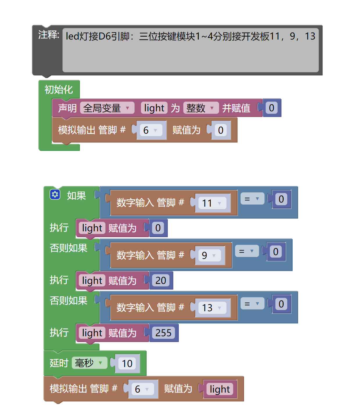
//led灯接D6引脚:四位按键模块1~4分别接开发板11,9,13
//
//
if (digitalRead(11) == 0) {
light = 0;
} else if (digitalRead(9) == 0) {
light = 20;
} else if (digitalRead(13) == 0) {
light = 255;
}
delay(10);
analogWrite(6, light);
}Example Program (ESP32 Development Board — Based on Python language, cannot be uploaded using Arduino IDE):
6, Miciqi Mixly Example Program (Graphical Language)
Example program:Click to download
Example Program (ESP32 Development Board): Click to download
7, Test Environment Setup
Setting up the Arduino Environment
Prepare Components:
HELLO STEM UNO R3 DEVELOPMENT BOARD *1
HELLO STEM UNO R3 P EXPANSION BOARD *1
USB TYPE-C DATA CABLE *1
LED module (HS-F08L) *1
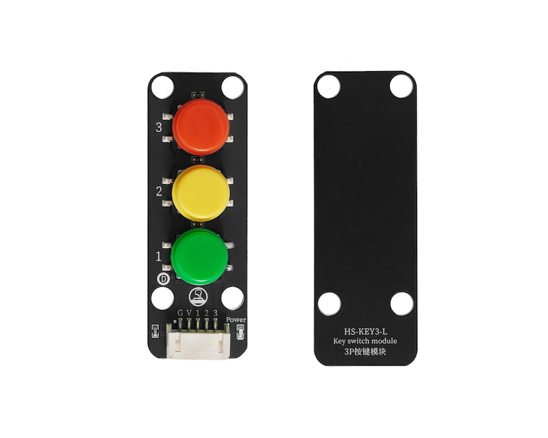
3-Simulated Pushbutton Module (HS-KEY3-L) *1
PH2.0 5P double-ended terminal line *1
PH2.0 3P dual headed terminal line *1
Circuit wiring diagram:
Set up Micropython environment
Prepare Components:
Circuit wiring diagram:
8. Video tutorial
Video tutorial: Click to view
9. Test conclusion
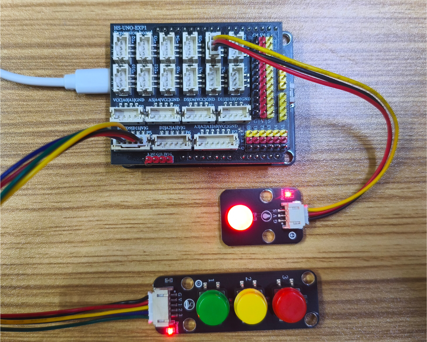
After the device is connected to the wire, burn the above program to the UNO-R3 PRO development board and then connect the power supply. Pressing different buttons will also change the brightness of the LED.