1. Introduction
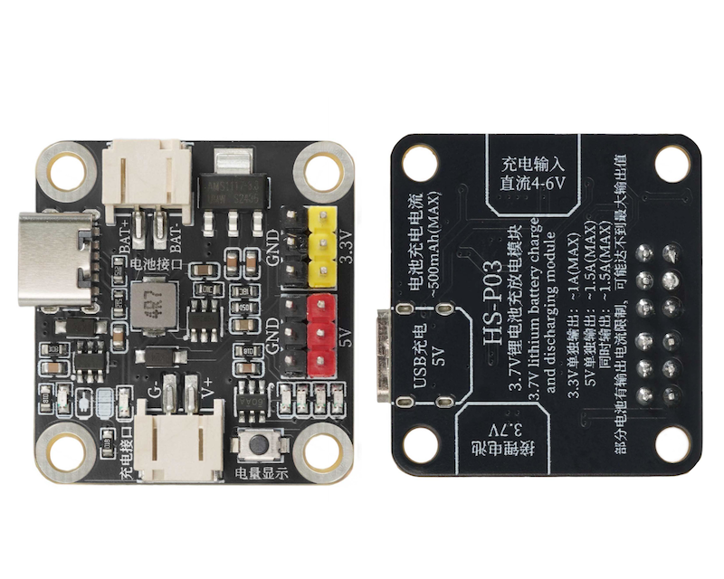
The module can display the battery power by pressing the switch, and the red charging indicator light will turn on when charging, providing a direct display of the charging status.When the battery is fully charged, the full charge indicator light turns on to indicate that charging is complete.Supports multiple charging input methods, capable of accepting DC 4-6V input.Equipped with a Type-C 5V charging port, and also has a USB charging 5V interface.It can provide various voltage outputs, including 3.3V and 5V output interfaces, which can meet the needs of different electrical equipment.3.3V maximum output current is about 1A, 5V maximum output current is about 1.5A, and when outputting simultaneously, the maximum current is about 1.5A. However, due to the inherent limitations of some batteries, the actual output may not reach the maximum value.
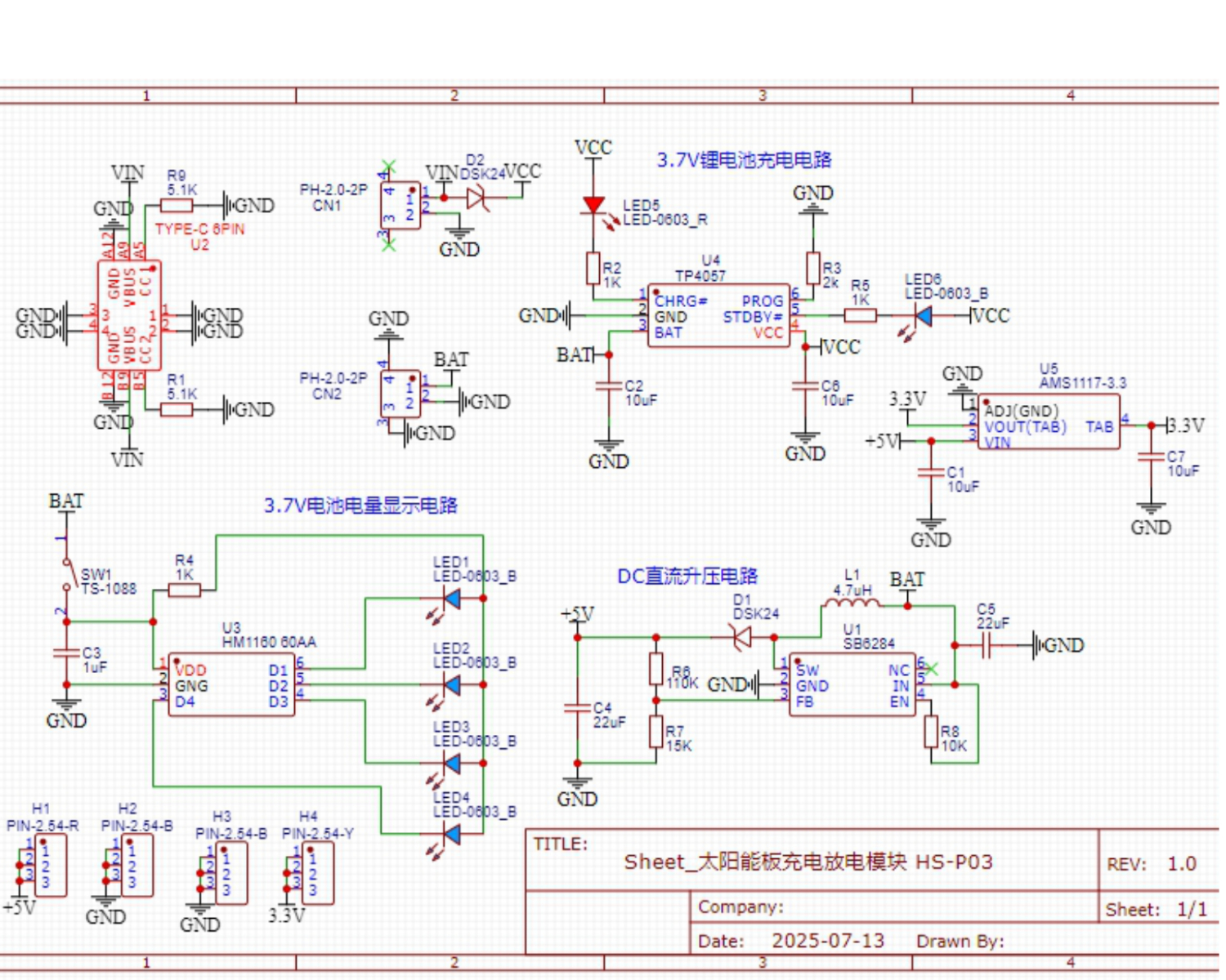
2. Schematic
Module Parameters
Pin Name | description |
|---|---|
G | GND (negative power output) |
5V | VCC (Power output positive terminal) |
3.3V | VCC (Power output positive terminal) |
Power Supply Voltage: 3.3V / 5V
Connection method: PH2.0 terminal wire
Installation method: Screw fixed
Operating temperature: 40°~80℃
Charging: Red indicator light is on
Charging complete: Blue indicator light is on
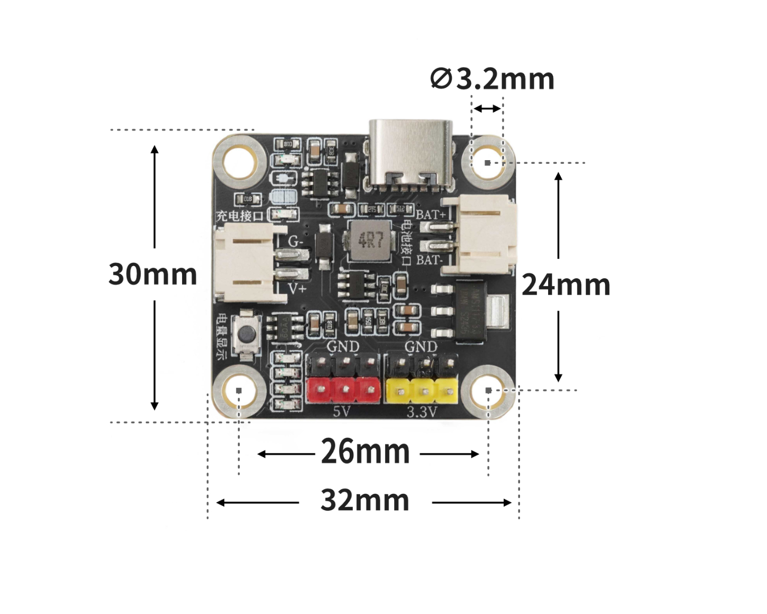
4, Circuit Board Size
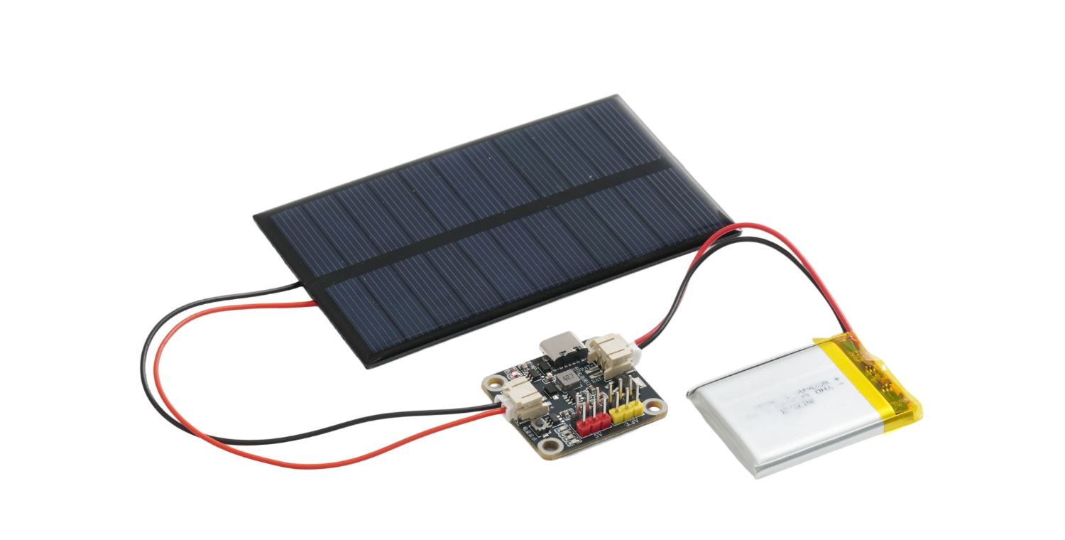
5, Test Environment Setup
Test Environment Setup
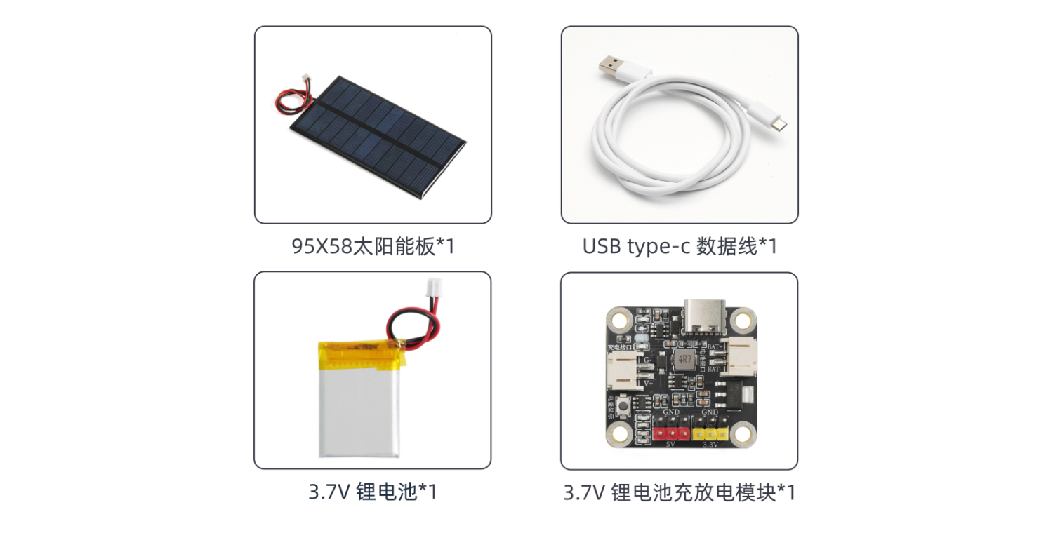
Prepare Components:
Magnetic Suction Electromagnet Module (HS-P03) *1
3.3v Battery Pack
Solar Photovoltaic Panel
Accessories:
6, Video Tutorial
Video Tutorial: Click to view
7, Test Conclusion
Test Conclusion:
Connect the photovoltaic panel wire and battery pack, place it under direct sunlight (definitely direct sunlight), and after a while, you can observe the red indicator light come on, indicating that the charging is successful.