
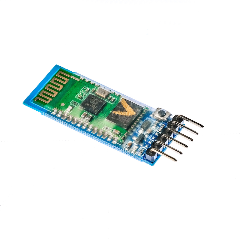
1. Introduction
HC-05 Bluetooth is a master-slave Bluetooth serial port module. Simply put, after a Bluetooth device is paired and connected to another Bluetooth device successfully, we can ignore the internal communication protocol of Bluetooth and use Bluetooth as a serial port directly.When a connection is established, two devices share the same channel, which is the same serial port, one device sends data to the channel, and the other device can receive the data in the channel.
2 Module Parameters
Pin Name | description |
|---|---|
RXD | Receiving end connected to the serial port module's TX |
TXD | Transmitting end connected to the serial port module's RX |
GND | The negative power supply terminal is connected to the GND of the serial port module |
VCC | The positive power supply terminal (5V) is connected to the VCC of the serial port module |
EN | Set the working mode (1, Working mode 2, AT command setting mode) has been brought out as a black small button on the module |
Voltage: DC3.3--5V
Module working role: Slave mode
Serial port parameters: 38400 bits/s, 1 stop bit, no parity
Pairing code: 1234
Device name: HC-05
Connection mode: Any Bluetooth device connection mode (restore default settings AT command: AT+ORGL)
The core module uses the HC-05 module, the interface includes VCC, GND, TXD, RXD, KEY pins, and the Bluetooth connection status output pin (STATE), low output when not connected, and high output after connection.
The LED indicates the Bluetooth connection status. A quick flash of the red and blue lights indicates no Bluetooth connection. A slow flash (the red and blue lights flash together every 2 seconds) indicates entering AT mode, and a double flash (the red and blue lights flash together twice in one second) indicates that Bluetooth is connected and the port is open.
Set the PCB with a reverse polarity protection diode, with 3.3V LDO, input voltage 3.6-6V, current about 30mA when not paired, about 10mA after pairing, input voltage is prohibited to exceed 7V!
Interface voltage 3.3V, can be directly connected to various microcontrollers (51, AVR, PIC, ARM, MSP430, etc.), 5V microcontrollers can also be directly connected, no need for MAX232 and cannot pass through MAX232!
The effective distance in open space is 10 meters (power level CLASS 2), it is also possible to exceed 10 meters, but no guarantee is made for the connection quality at this distance.
After pairing, it can be used as a full-duplex serial port without the need to understand any Bluetooth protocol. It supports 8-bit data bits, 1 stop bit, and communication formats that can be set with even or odd parity. This is the most commonly used communication format and does not support other formats.
You can enter the AT command mode by pulling up the 34th pin to set parameters and query information.
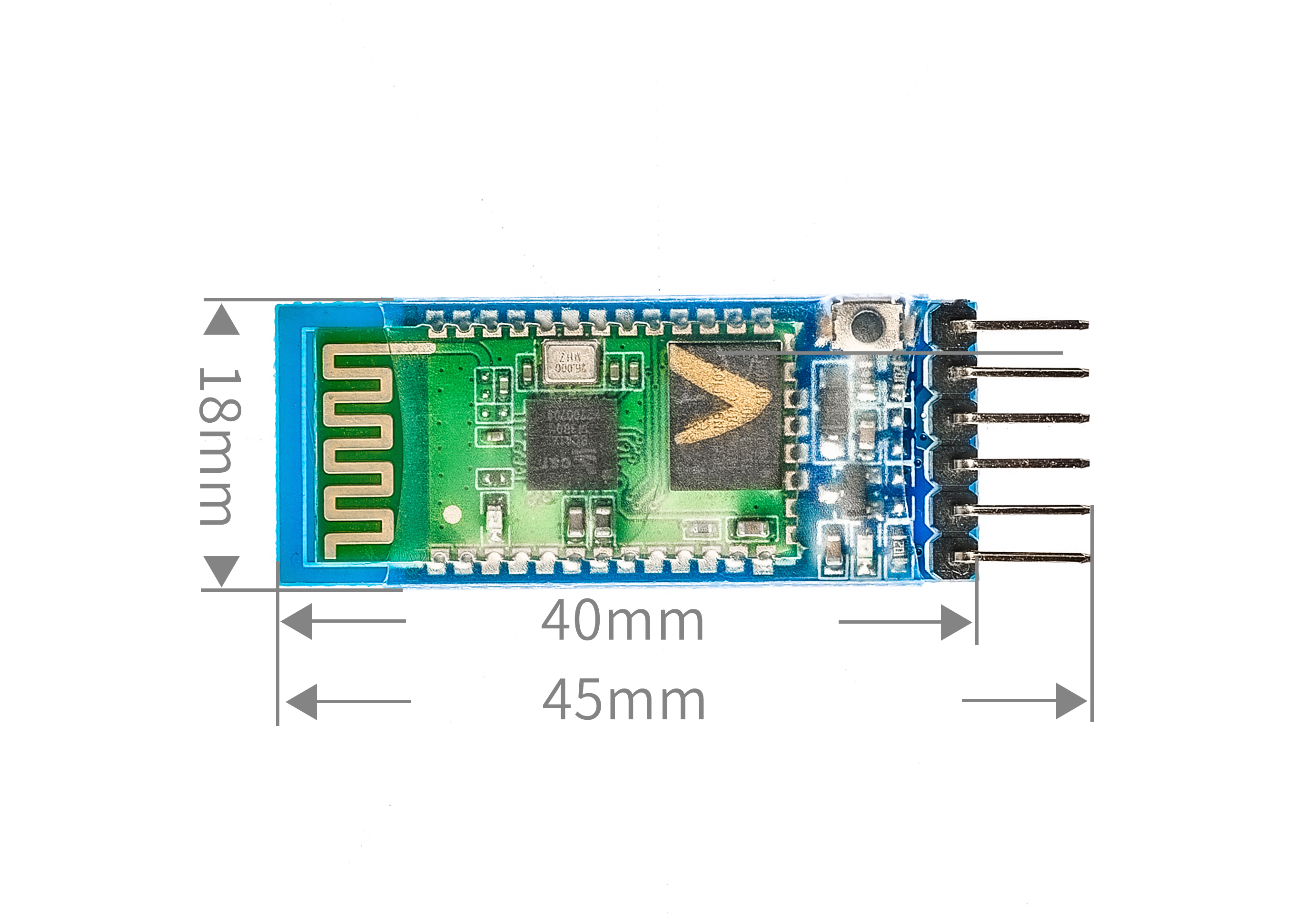
Compact (3.57cm*1.52cm), factory sticker production, ensuring sticker quality. Also fitted with a transparent shrink tube, dustproof and aesthetically pleasing, and has a certain static-proof ability.
Can be switched to host or slave mode via AT command, can connect to specified devices via AT command.
Supports from 4800bps to 1382400bps.
Control signal: serial communication.
3, circuit board size
4. Arduino IDE example program
Attention: If prompted with an error message about the library file during program upload, please import the library file first!
Arduino IDE Library Download and Import Tutorial:Click to view
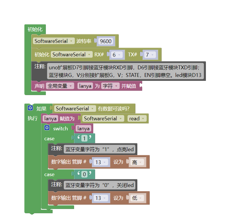
Example program (UNO development board):
#include <SoftwareSerial.h>
SoftwareSerial mySerial(6, 7);
char lanya = 0;
void setup() {
mySerial.begin(9600);
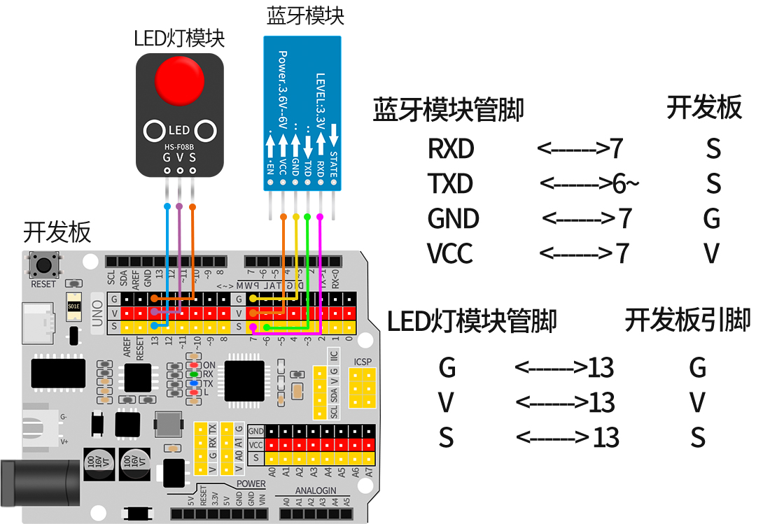
//uno扩展板D7引脚接蓝牙模块RXD引脚,D6引脚接蓝牙模块TXD引脚;
//蓝牙模块G,V分别接扩展板G,V;STATE,EN引脚悬空。led模块D13
pinMode(13, OUTPUT);
}
void loop() {
if (mySerial.available() > 0) {
lanya = mySerial.read();
switch (lanya) {
case '1':
//蓝牙变量字符为“1”,点亮led
digitalWrite(13, HIGH);
break;
case '0':
//蓝牙变量字符为“0”,关闭led
digitalWrite(13, LOW);
break;
}
}
}5, ESP32 Python Example (for Mixly IDE / Mixly)
Choose the development board Python ESP32 [ESP32 Generic(4MB)] and upload in code mode
Attention: If prompted with an error message about the library file during program upload, please import the library file first!
Download and import tutorial for Mixly IDE ESP32 library:Click to view
Example program (ESP32-Python):
待更新...6, Miciqi Mixly Example Program (Graphical Language)
Example program (UNO development board):Click to download
Attention: If prompted with an error message about the library file during program upload, please import the library file first!
Download and import tutorial of Mixly IDE Arduino library:Click to view
Example Program (ESP32 Development Board):Click to download
Attention: If prompted with an error message about the library file during program upload, please import the library file first!
Download and import tutorial for Mixly IDE ESP32 library:Click to view
Image pending update...
7, Test Environment Setup
Arduino UNO Test Environment Setup
Prepare Components:
HELLO STEM UNO R3 PRO DEVELOPMENT BOARD *1
USB TYPE-C DATA CABLE *1
LED light module (HS-F08A) *1
Bluetooth module (hc-05) *1
1P female to female DuPont wire *3 pieces or 3P female to female DuPont wire *1 piece
2P female-to-female Dupont wire *2 pieces
Android phone * 1 unit
Circuit wiring diagram:
ESP32 Test Environment Setup
Prepare Components:Pending update...
Circuit wiring diagram:Pending update...
8, Install Bluetooth Serial Communication App on Mobile Phone
You can search for Bluetooth Serial Port Assistant in the APP market, generally third-party ones can be used, if you can't find it, we have placed a download link for an APK (1_base) software (Bluetooth debugger) on our official website, which can be imported into the phone and installed.First open the software, then connect Bluetooth.
Bluetooth software:Click to download
1. Open the app
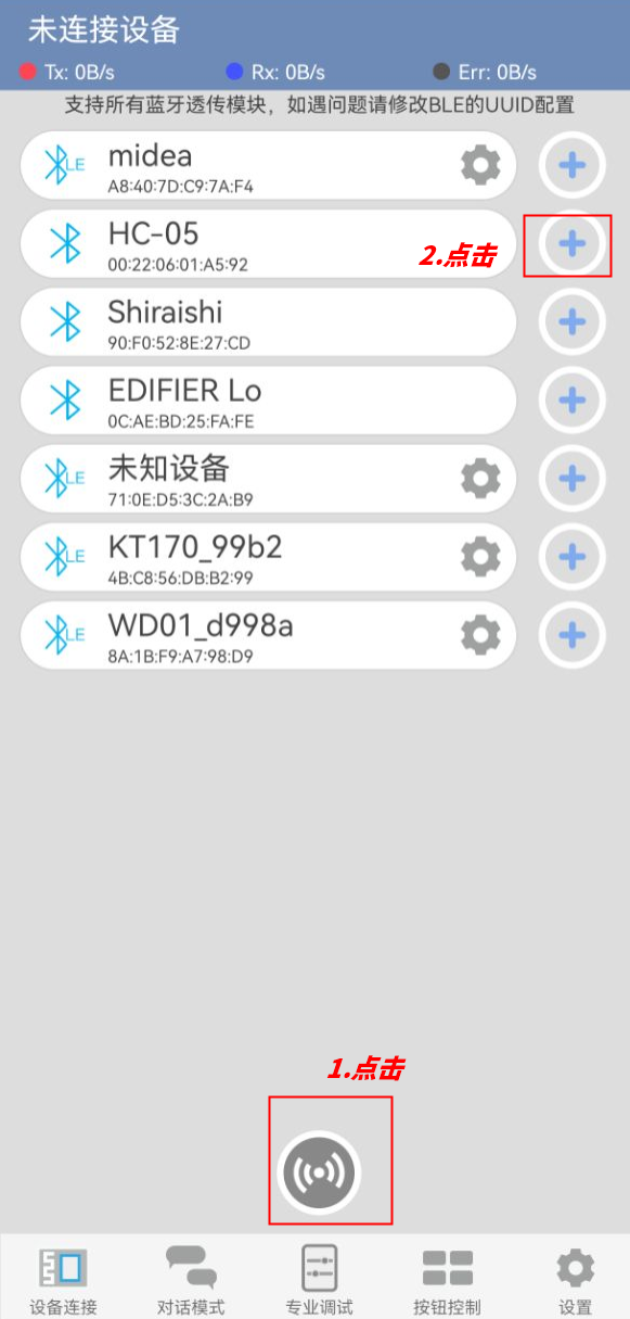
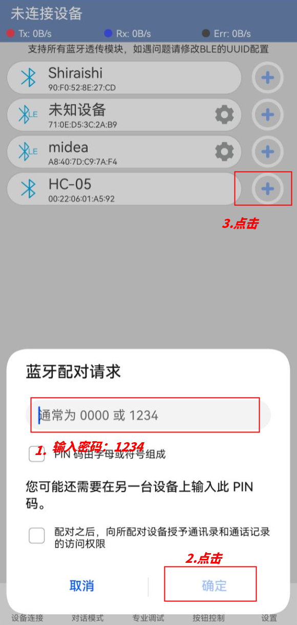
2. Pair HC-05 Bluetooth module
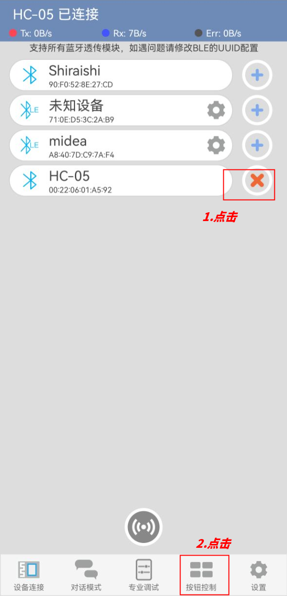
3. After connecting Bluetooth, open the button control interface
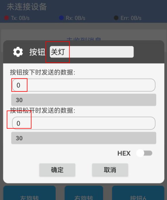
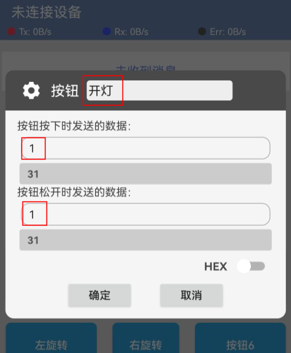
4. Edit button control led
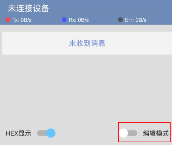
5. Enter dialogue mode to control led

9, Video tutorial
Video tutorial:Click to view
10, Test results
Arduino UNO test results:
After the device is connected to the wire, upload the above program to the Arduino UNO development board, then open the mobile app software, connect Bluetooth, enter edit mode to set the data sent by the two buttons, and then exit edit mode.When the Arduino Uno receives data '1', the LED light turns on, and when it receives data '0', the LED light turns off.We also enter the dialogue mode to send data "1" or send data "0" to control the LED on and off.
ESP32 Test Results:
Pending update...