
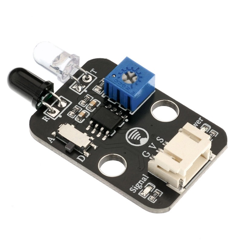
1. Introduction
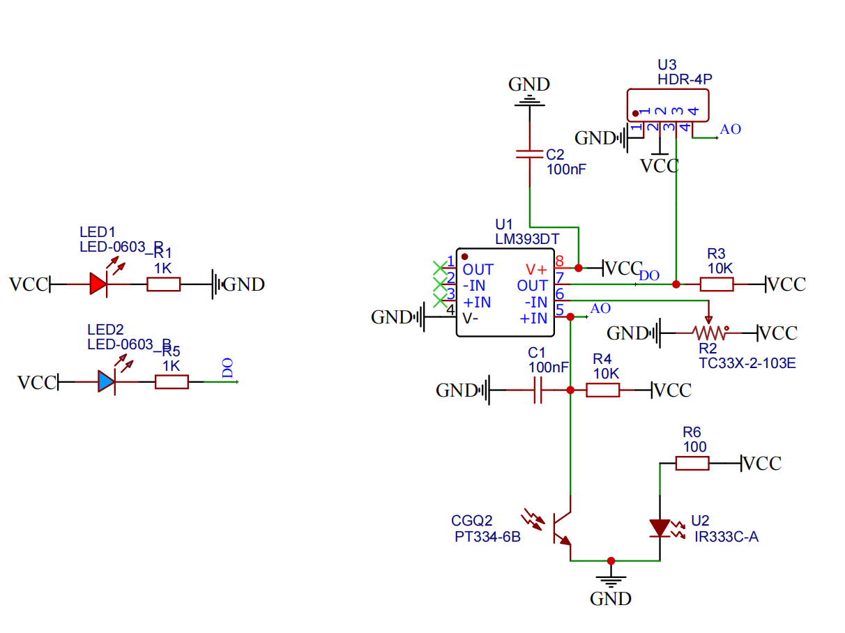
2. Schematic
Module Parameters
Pin Name | description |
|---|---|
G | GND (Negative Power Input) |
V | VCC (Positive Power Input) |
S | Signal Pin |
D | Digital Signal Pin |
A | Analog Signal Pin |
Power Supply Voltage: 3.3V / 5V
Connection method: PH2.0 terminal wire
Installation Method: Double Screw Fixed
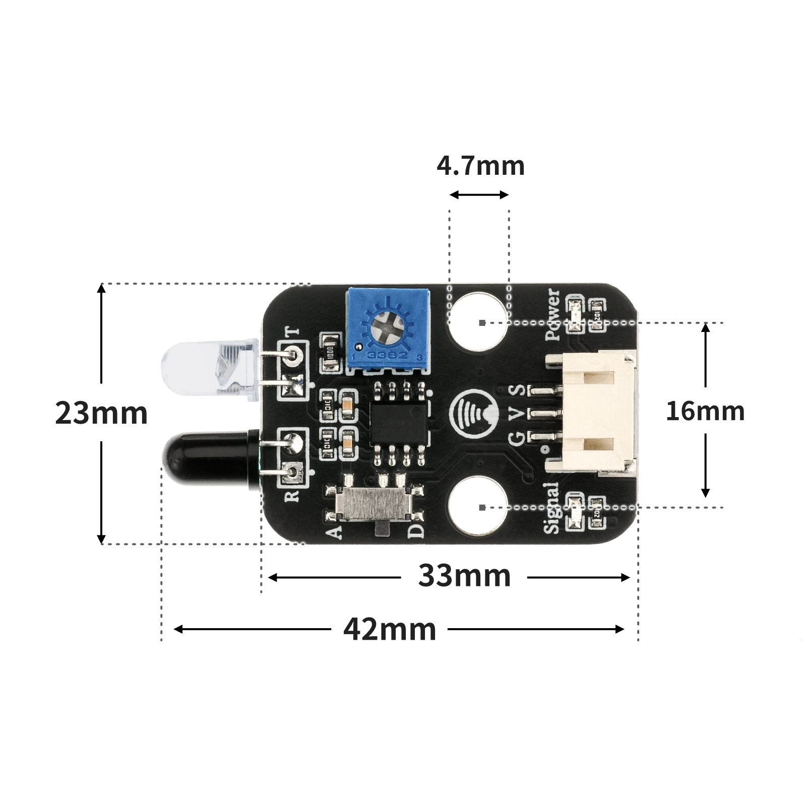
4, Circuit Board Size
5 of Arduino IDE example program
Arduino UNO Example (for Mixly IDE, Arduino IDE):
void setup(){
pinMode(4, INPUT);//设置D4为输入模式
pinMode(6, OUTPUT);//设置D6为输出模式
}
void loop(){
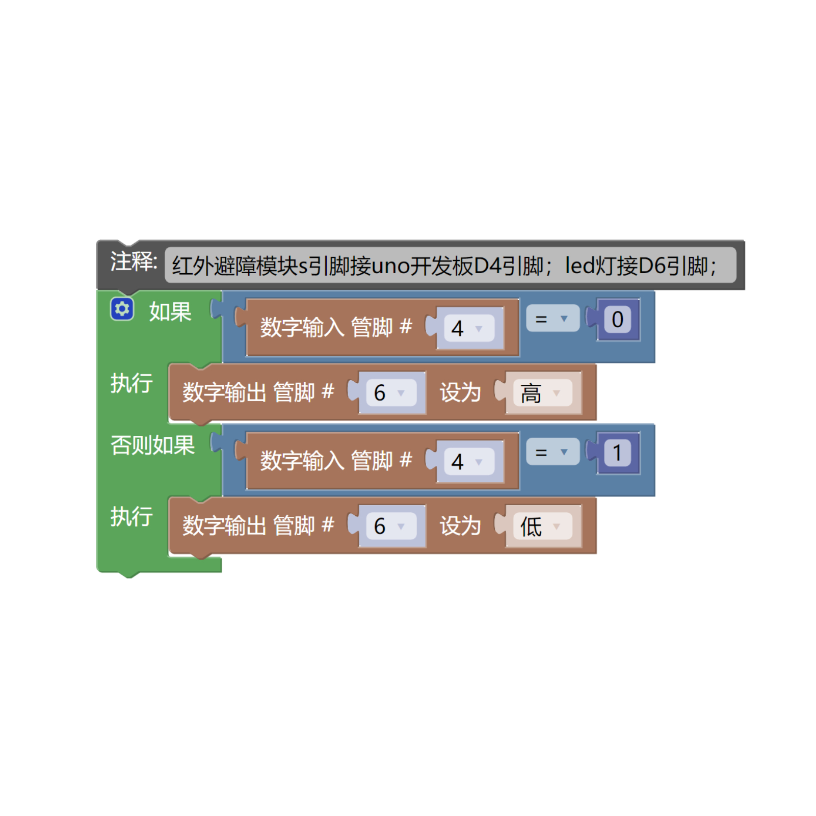
//红外避障模块s引脚接uno开发板D4引脚,A引脚空置;led灯接D6引脚;
if (digitalRead(4) == 0) {//检测到障碍物,输出低电平
digitalWrite(6,HIGH);//亮灯
} else if (digitalRead(4) == 1) {//未检测到障碍物,输出高电平
digitalWrite(6,LOW);//熄灭
}
}ESP32 Python Example (for Mixly IDE / Micskit)
(Choose the Python ESP32 [ESP32 Generic(4MB)] to switch to code mode upload):
import machine
import time
pin2 = machine.Pin(2, machine.Pin.IN)
pin4 = machine.Pin(4, machine.Pin.OUT)
while True:
if pin2.value() == 0:
pin4.value(1)
time.sleep(1)
else:
pin4.value(0)
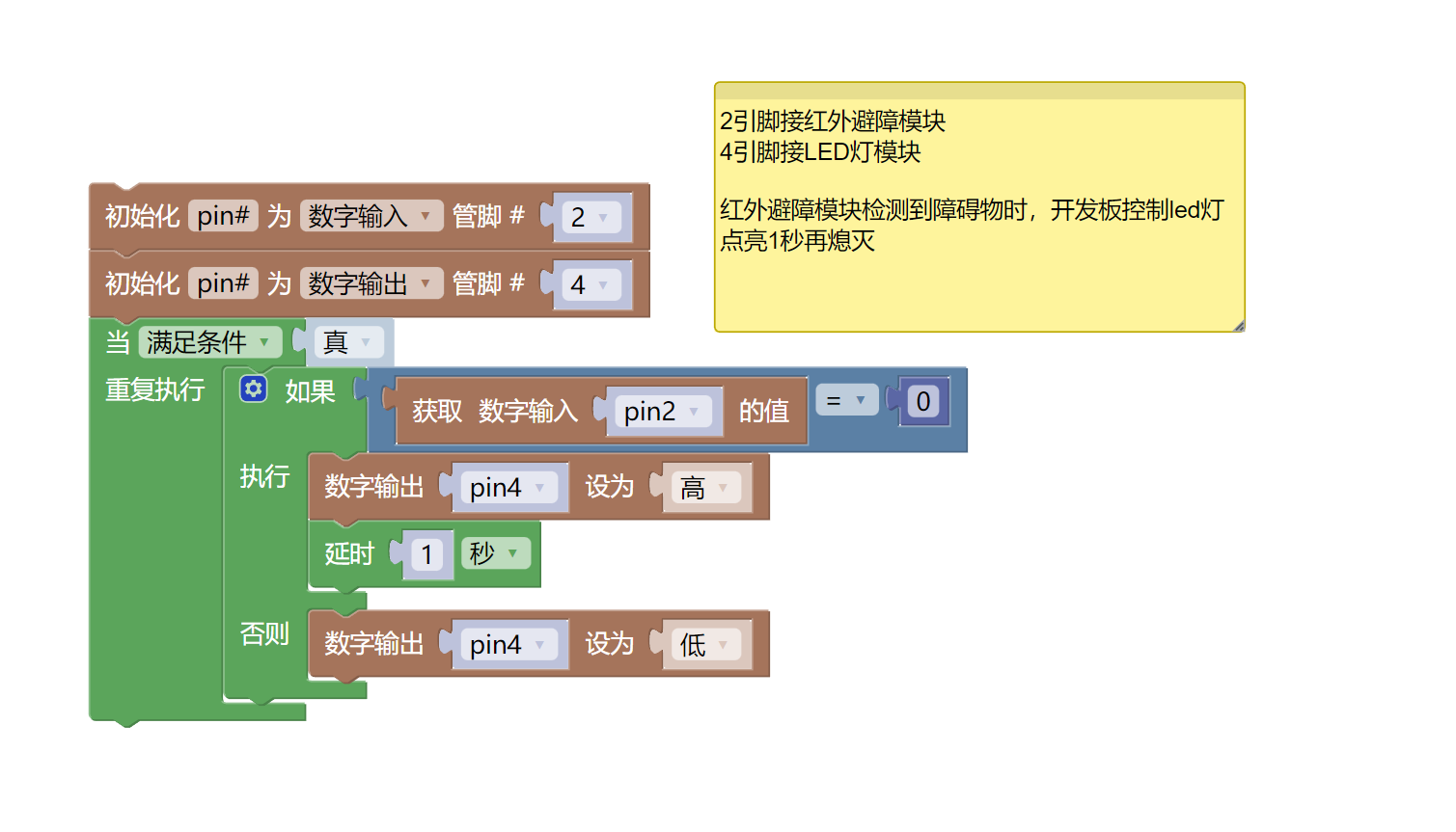
6, Miciqi Mixly Example Program (Graphical Language)
Arduino UNO Graphical Example Program:Click to download
ESP32 Python Graphical Example Program:Click to download
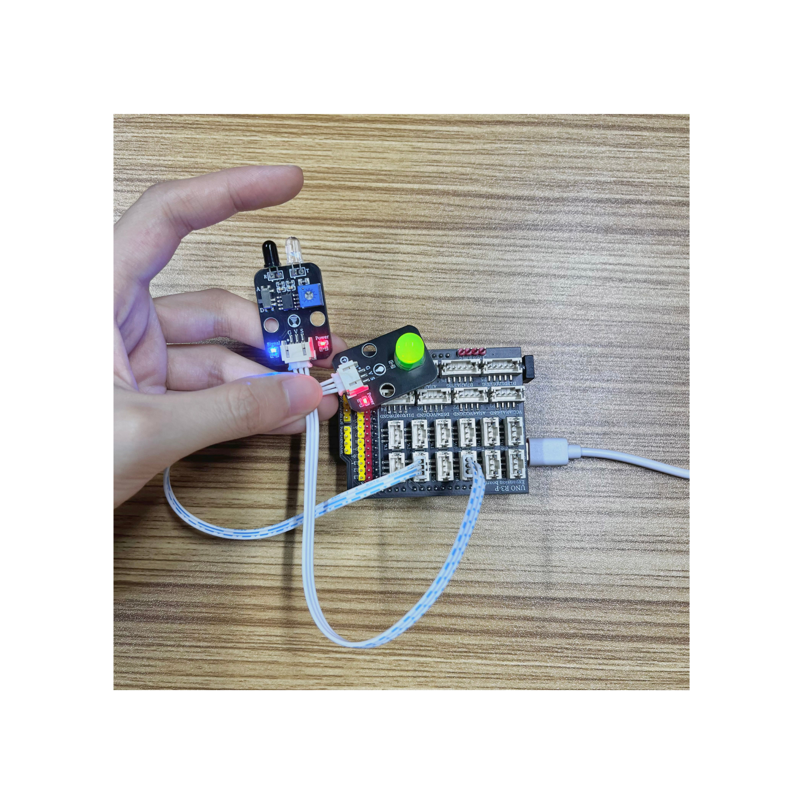
7, Test Environment Setup
Arduino UNO Test Environment Setup
Prepare Components:
HELLO STEM UNO R3 DEVELOPMENT BOARD *1
HELLO STEM UNO R3 P EXPANSION BOARD *1
USB TYPE-C DATA CABLE *1
LED module (HS-F08L) *1
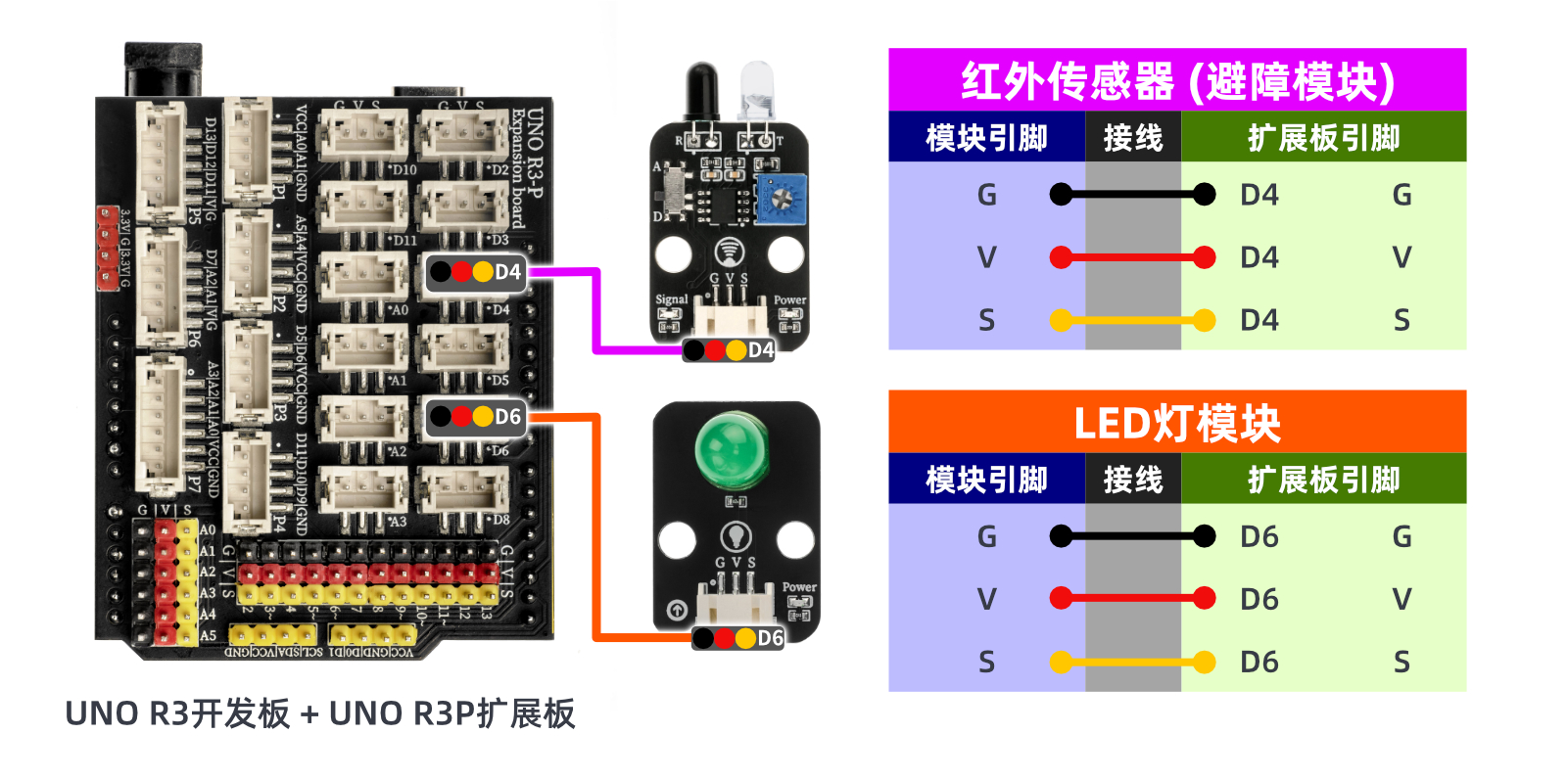
Infrared Obstacle Avoidance Module (HS-S02L) *1
PH2.0 3P dual-head terminal line *2
Circuit wiring diagram:
ESP32 Python test environment setup
8. Video tutorial
Arduino UNO video tutorial:Click to view
ESP32 Python Video Tutorial:
9. Test conclusion
Arduino UNO Test Conclusion:
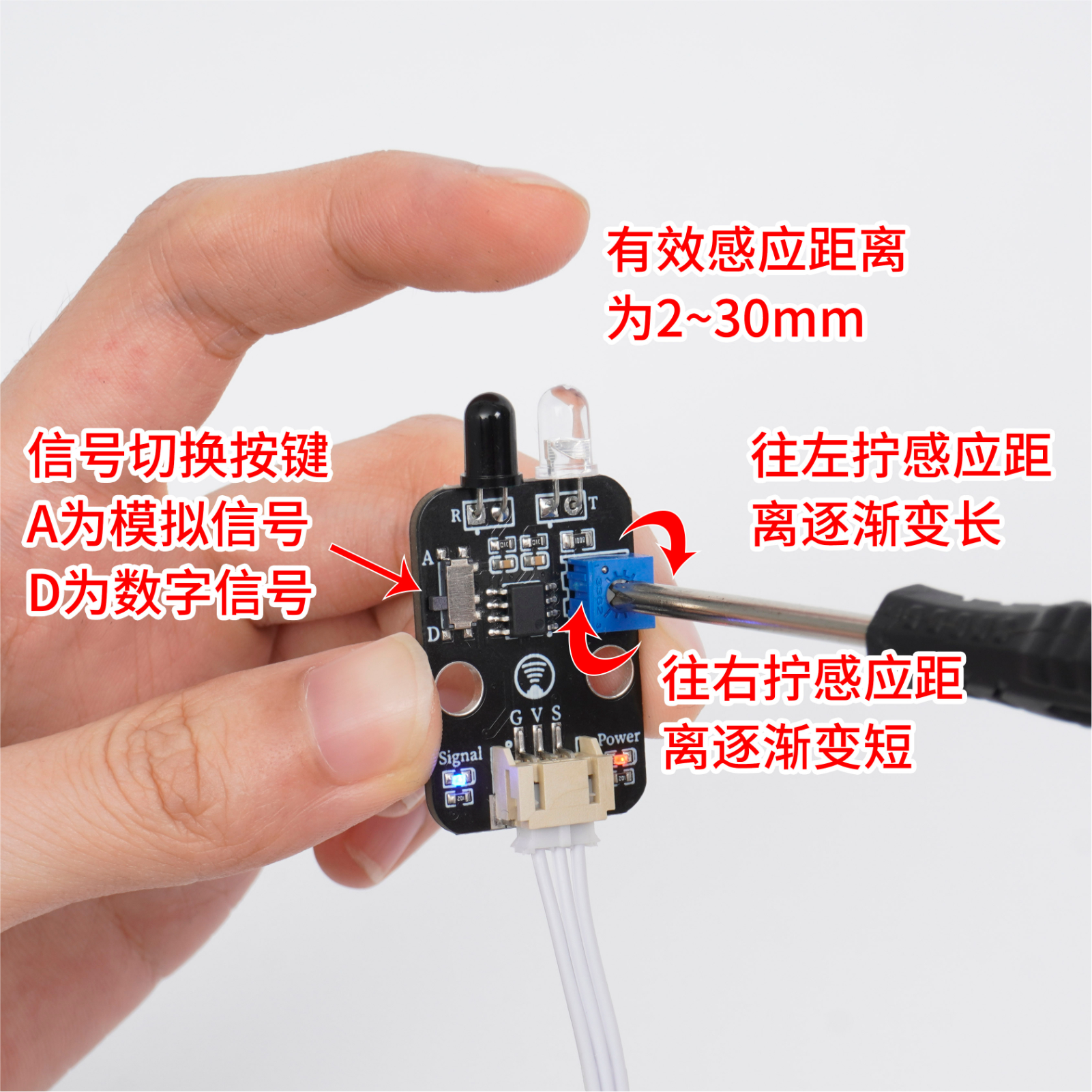
Module debugging:Under the condition that the infrared obstacle avoidance module is powered on, adjust the potentiometer of the infrared obstacle avoidance module with a small screwdriver, so that the finger is about 20mm away from the infrared obstacle avoidance probe, the sensor signal indicates the blue light is on, and the infrared obstacle avoidance module signal indicates the blue light is off when the finger is about 20mm away from the probe.Note: The infrared emitting and receiving probes of the infrared obstacle avoidance module are greatly interfered by the ambient light, please do not debug in a strong sun environment.
The infrared obstacle avoidance module utilizes the working characteristics of infrared. When the infrared obstacle avoidance module sensor detects an obstacle, it outputs a low level (0); the LED light is turned on. When the infrared obstacle avoidance module sensor does not detect any obstacle ahead, it outputs a high level (1), and the LED light is off.
ESP32 Python test conclusion:
Module debugging:Under the condition that the infrared obstacle avoidance module is powered on, adjust the potentiometer of the infrared obstacle avoidance module with a small screwdriver, so that the finger is about 20mm away from the infrared obstacle avoidance probe, the sensor signal indicates the blue light is on, and the infrared obstacle avoidance module signal indicates the blue light is off when the finger is about 20mm away from the probe.Note: The infrared emitting and receiving probes of the infrared obstacle avoidance module are greatly interfered by the ambient light, please do not debug in a strong sun environment.
The infrared obstacle avoidance module utilizes the working characteristics of infrared. When the infrared obstacle avoidance module sensor detects an obstacle, it outputs a low level (0); the LED light is turned on. When the infrared obstacle avoidance module sensor does not detect any obstacle ahead, it outputs a high level (1), and the LED light is off.