
1. Introduction
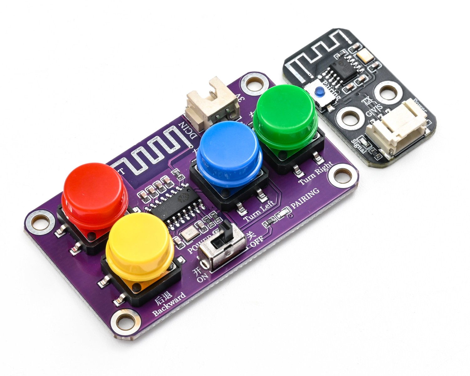
2.4G 4-channel wireless remote controller and配套 remote signal receiver module, using 2.4GHz digital wireless communication technology, strong anti-interference ability, long control distance and no directional limitation;The remote control provides 4 independent control channels to meet various operation requirements such as forward, backward, turning, and function switching. The receiver is responsible for receiving and decoding wireless signals, outputting stable serial communication signals, supporting one-key pairing and power-off memory, automatically entering a safe state when the signal is lost. When used together, they can realize stable and reliable long-distance wireless control for intelligent devices such as tracking cars and robots, with simple wiring and compatibility with various development boards and expansion boards.
2. Schematic
HS-S84P 2.4G remote control signal receiver Click to view
Module Parameters
Pin Name | description |
|---|---|
G | GND (Negative Power Input) |
V | VCC (Positive Power Input) |
S | Signal Pin |
Power Supply Voltage: 3.3V / 5V
Connection method: PH2.0 terminal wire
Installation method: Screw fixed
4, Circuit Board Size

5 of Arduino IDE example program
Attention: If prompted with an error message about the library file during program upload, please import the library file first!
Arduino IDE Library Download and Import Tutorial:Click to view
Example program (UNO development board):
#include <SoftwareSerial.h>

SoftwareSerial mySerial1(10,11);
uint8_t rxFrame[6]={0};

volatile uint8_t rxIndex;
volatile uint8_t data;

void setup(){
  mySerial1.begin(9600);
  rxIndex = 0;
  data = 0;
  Serial.begin(9600);
}

void loop(){
  if (mySerial1.available()) {
    data = mySerial1.read();
    if (rxIndex == 0) {
      if (data == 0xAA) {
        rxFrame[rxIndex] = data;
        rxIndex = rxIndex + 1;

      }

    } else {
      rxFrame[rxIndex] = data;
      rxIndex = rxIndex + 1;
      if (rxIndex == 6) {
        rxIndex = 0;
        for (int i = 0; i <= 5; i = i + (1)) {
          Serial.write(rxFrame[i]);
        }
        Serial.println("");

      }

    }

  }

}
6, ESP32 Python Example (for Mixly IDE/Misashi)
Choose the development board Python ESP32 [ESP32 Generic(4MB)] and upload in code mode
Attention: If prompted with an error message about the library file during program upload, please import the library file first!
Download and import tutorial for Mixly IDE ESP32 library:Click to view
Example program (ESP32-Python):Pending update...
7, Mixly example program (graphical language)
Example program:Click to download
Attention: If prompted with an error message about the library file during program upload, please import the library file first!
Download and import tutorial of Mixly IDE Arduino library:Click to view

Example Program (ESP32 Development Board):Click to download
Attention: If prompted with an error message about the library file during program upload, please import the library file first!
Download and import tutorial for Mixly IDE ESP32 library:Click to view
Image pending update...
8. Setting up the Test Environment
Arduino UNO Test Environment Setup
Prepare Components:
HELLO STEM UNO R3 DEVELOPMENT BOARD *1
HS-UNO-EXP1 expansion board*1
USB TYPE-C DATA CABLE *1
2.4G 4-channel wireless remote control*1
2.4G wireless remote signal receiver module *1
5# battery box *1
PH2.0 double-ended terminal line *1
Circuit wiring diagram:

ESP32 Test Environment Setup
Prepare Components:Pending update...
Circuit wiring diagram:Pending update...
9, Video tutorial
Video tutorial:Pending update...
10, Test results
Arduino UNO test results:
After the device is connected with the wires, burn the above program to the Arduino UNO development board, and connect the power supply.Wait for the wireless remote controller and remote signal receiver to connect, then press any key to view the received data packets through the serial port.
ESP32 Test Results:
Pending update...