1、소개
심장 박동 횟수와 리듬을 모니터링하는 전자 장치로, 의료 건강, 운동 건강, 인공 신체 장비 등 다양한 분야에서 널리 사용됩니다。
2、시뮬레이션 그래프
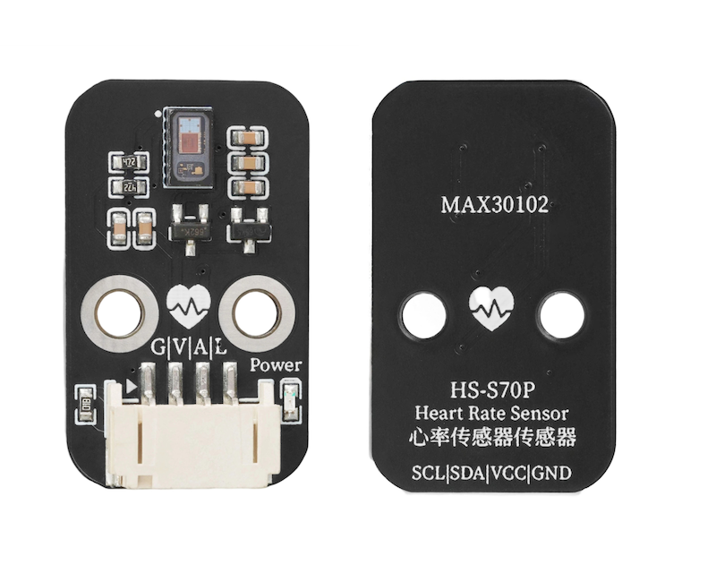
3、모듈 매개변수
핀 이름 | 설명 |
|---|---|
GND | GND(전원 입력 부정极) |
VCC | VCC(전원 입력 정극) |
A | IIC 데이터 전송 패인트 |
L | IIC 통신 클록 패인트 |
전원 전압: 3.3V - 5V
연결 방식: PH2.0 4P 핀 라인
安装方式:螺丝固定
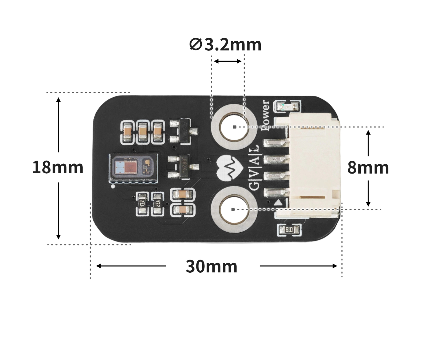
4、회로판 크기
5、아두이노 IDE 예제 프로그램
주의: 프로그램을 업로드할 때 라이브러리 파일 오류가 표시되면 먼저 라이브러리 파일을 가져오세요!
Arduino IDE 라이브러리 다운로드 및 导入 가이드:点击查看
예제 프로그램(UNO 개발 보드):
#include <Wire.h>
#include "MAX30105.h"
#include "heartRate.h"

MAX30105 particleSensor;
const byte RATE_SIZE = 4; //Increase this for more averaging. 4 is good.
 byte rates[RATE_SIZE]; //Array of heart rates
 byte rateSpot = 0;
 long lastBeat = 0; //Time at which the last beat occurred
 float beatsPerMinute;
 int Bpm_value;

void setup(){
  Serial.begin(9600);
  particleSensor.begin(Wire, I2C_SPEED_FAST);
  particleSensor.setup(); //Configure sensor with default settings
  particleSensor.setPulseAmplitudeRed(0x0A); //Turn Red LED to low to indicate sensor is running
  particleSensor.setPulseAmplitudeGreen(0); //Turn off Green LED

}

void loop(){
  long irValue = particleSensor.getIR();
  if (checkForBeat(irValue) == true)
    {
      //We sensed a beat!
      long delta = millis() - lastBeat;
      lastBeat = millis();
      beatsPerMinute = 60 / (delta / 1000.0);
      if (beatsPerMinute < 255 && beatsPerMinute > 20)
      {
        rates[rateSpot++] = (byte)beatsPerMinute; //Store this reading in the array
        rateSpot %= RATE_SIZE; //Wrap variable
        //Take average of readings
  Bpm_value = 0;
        for (byte x = 0 ; x < RATE_SIZE ; x++)
  Bpm_value += rates[x];
  Bpm_value /= RATE_SIZE;
      }
    }
    Serial.print("Bpm_value = ");
    Serial.print(Bpm_value);
    Serial.println(" bpm");

}
6、ESP32 Python 예제(Mixly IDE /미스키에 적용됨)
개발 보드를 선택하세요 Python ESP32 【ESP32 Generic(4MB)】를 코드 모드로 전환하여 업로드하십시오
주의: 프로그램을 업로드할 때 라이브러리 파일 오류가 표시되면 먼저 라이브러리 파일을 가져오세요!
미시지(Mixly)IDE ESP32 라이브러리 다운로드 및 가져오기 가이드:点击查看
예제 프로그램(ESP32-Python):
from machine import I2C, Pin
import time

MAX3010X_I2C_ADDR = 0x57
REG_FIFOWRITEPTR   = 0x04
REG_FIFOOVERFLOW   = 0x05
REG_FIFOREADPTR    = 0x06
REG_FIFODATA       = 0x07
REG_FIFOCONFIG     = 0x08
REG_MODECONFIG     = 0x09
REG_PARTICLECONFIG = 0x0A
REG_LED1_PA        = 0x0C
REG_LED2_PA        = 0x0D
REG_MULTILEDCONFIG1= 0x11
REG_MULTILEDCONFIG2= 0x12
REG_PARTID         = 0xFF
EXPECTED_PARTID    = 0x15

def _mask_write(i2c, addr, reg, mask, bits):
    cur = i2c.readfrom_mem(addr, reg, 1)[0]
    cur &= mask
    cur |= bits
    i2c.writeto_mem(addr, reg, bytes([cur]))

class MAX3010x:
    def __init__(self, i2c, address=MAX3010X_I2C_ADDR):
        self.i2c = i2c
        self.address = address

    def read_reg(self, reg):
        return self.i2c.readfrom_mem(self.address, reg, 1)[0]

    def write_reg(self, reg, val):
        self.i2c.writeto_mem(self.address, reg, bytes([val & 0xFF]))

    def soft_reset(self):
        _mask_write(self.i2c, self.address, REG_MODECONFIG, 0xBF, 0x40)
        t0 = time.ticks_ms()
        while time.ticks_diff(time.ticks_ms(), t0) < 100:
            if (self.read_reg(REG_MODECONFIG) & 0x40) == 0:
                return True
            time.sleep_ms(1)
        return False

    def setup(self):
        self.soft_reset()
        _mask_write(self.i2c, self.address, REG_FIFOCONFIG, 0b11100000, 0x40)
        _mask_write(self.i2c, self.address, REG_FIFOCONFIG, 0xEF, 0x10)
        _mask_write(self.i2c, self.address, REG_MODECONFIG, 0xF8, 0x03)
        _mask_write(self.i2c, self.address, REG_PARTICLECONFIG, 0x9F, 0x60)
        _mask_write(self.i2c, self.address, REG_PARTICLECONFIG, 0xE3, 0x00)
        _mask_write(self.i2c, self.address, REG_PARTICLECONFIG, 0xFC, 0x03)
        self.write_reg(REG_LED1_PA, 0x4F)
        self.write_reg(REG_LED2_PA, 0x4F)
        _mask_write(self.i2c, self.address, REG_MULTILEDCONFIG1, 0xF8, 0x01)
        _mask_write(self.i2c, self.address, REG_MULTILEDCONFIG1, 0x8F, 0x20)
        self.write_reg(REG_FIFOREADPTR, 0)
        self.write_reg(REG_FIFOOVERFLOW, 0)
        self.write_reg(REG_FIFOWRITEPTR, 0)

    def read_fifo_red_ir(self):
        if self.read_reg(REG_FIFOREADPTR) == self.read_reg(REG_FIFOWRITEPTR):
            return None
        data = self.i2c.readfrom_mem(self.address, REG_FIFODATA, 6)
        red = ((data[0] << 16) | (data[1] << 8) | data[2]) & 0x3FFFF
        ir  = ((data[3] << 16) | (data[4] << 8) | data[5]) & 0x3FFFF
        return red, ir

lastBeatTime = 0
threshold = 2000
peak = 0
trough = 999999
amp = 0
IBI = 600
firstBeat = True
secondBeat = False
rate = [600] * 10
rate_index = 0

def checkForBeat(ir_value):
    global threshold, peak, trough, amp
    global lastBeatTime, firstBeat, secondBeat
    global IBI, rate, rate_index
    now = time.ticks_ms()
    signal = ir_value
    if signal < threshold and signal < trough:
        trough = signal
    if signal > threshold and signal > peak:
        peak = signal
    if signal > threshold and (time.ticks_diff(now, lastBeatTime) > 300):
        IBI = time.ticks_diff(now, lastBeatTime)
        lastBeatTime = now
        if firstBeat:
            firstBeat = False
            secondBeat = True
            return False
        if secondBeat:
            secondBeat = False
            for i in range(len(rate)):
                rate[i] = IBI
        rate[rate_index] = IBI
        rate_index = (rate_index + 1) % len(rate)
        amp = peak - trough
        threshold = trough + amp * 0.5
        peak = threshold
        trough = threshold
        return True
    if time.ticks_diff(now, lastBeatTime) > 2500:
        threshold = signal * 0.97
        peak = threshold
        trough = threshold
        firstBeat = True
        secondBeat = False
    return False

def read_bpm(timeout_ms=8000):
    i2c = I2C(1, scl=Pin(22), sda=Pin(21), freq=400000)
    sensor = MAX3010x(i2c)
    sensor.setup()
    start = time.ticks_ms()
    while time.ticks_diff(time.ticks_ms(), start) < timeout_ms:
        data = sensor.read_fifo_red_ir()
        if not data:
            time.sleep_ms(5)
            continue
        red, ir = data
        if ir < 20000:
            continue
        if checkForBeat(ir):
            avg_IBI = sum(rate) / len(rate)
            bpm = 60000 / avg_IBI
            new_bpm = bpm - 80
            if new_bpm < 0:
                return 0
            else:
                return int(new_bpm)
    return 0

import machine


while True:
    xinlv = read_bpm()
    print(('心率值(BMP):' + str(xinlv)))
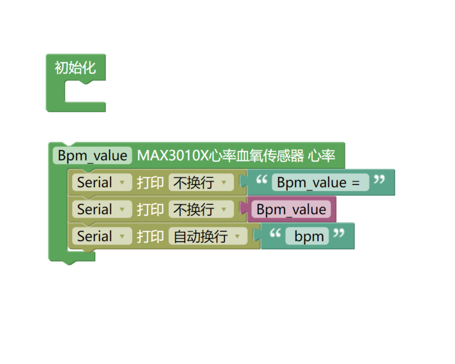
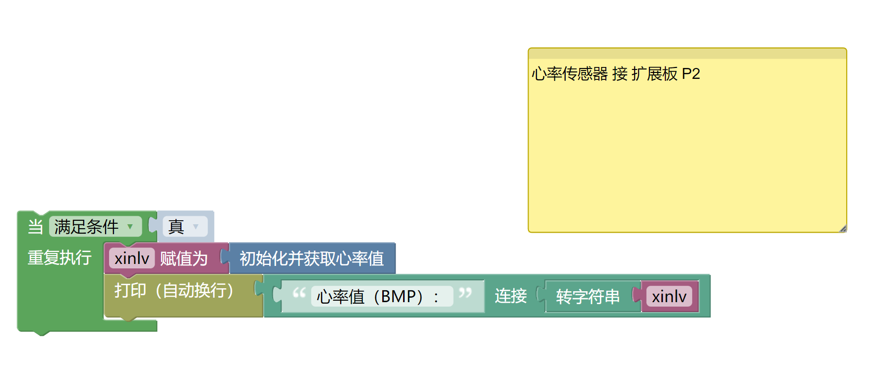
7、미스키 Mixly 예제 프로그램(그래픽 언어)
예제 프로그램(UNO 개발 보드):다운로드 클릭
주의: 프로그램을 업로드할 때 라이브러리 파일 오류가 표시되면 먼저 라이브러리 파일을 가져오세요!
미스키(Mixly)IDE Arduino 라이브러리 다운로드 및 가져오기 가이드:点击查看
예제 프로그램(ESP32 개발 보드):다운로드 클릭
주의: 프로그램을 업로드할 때 라이브러리 파일 오류가 표시되면 먼저 라이브러리 파일을 가져오세요!
미시지(Mixly)IDE ESP32 라이브러리 다운로드 및 가져오기 가이드:点击查看
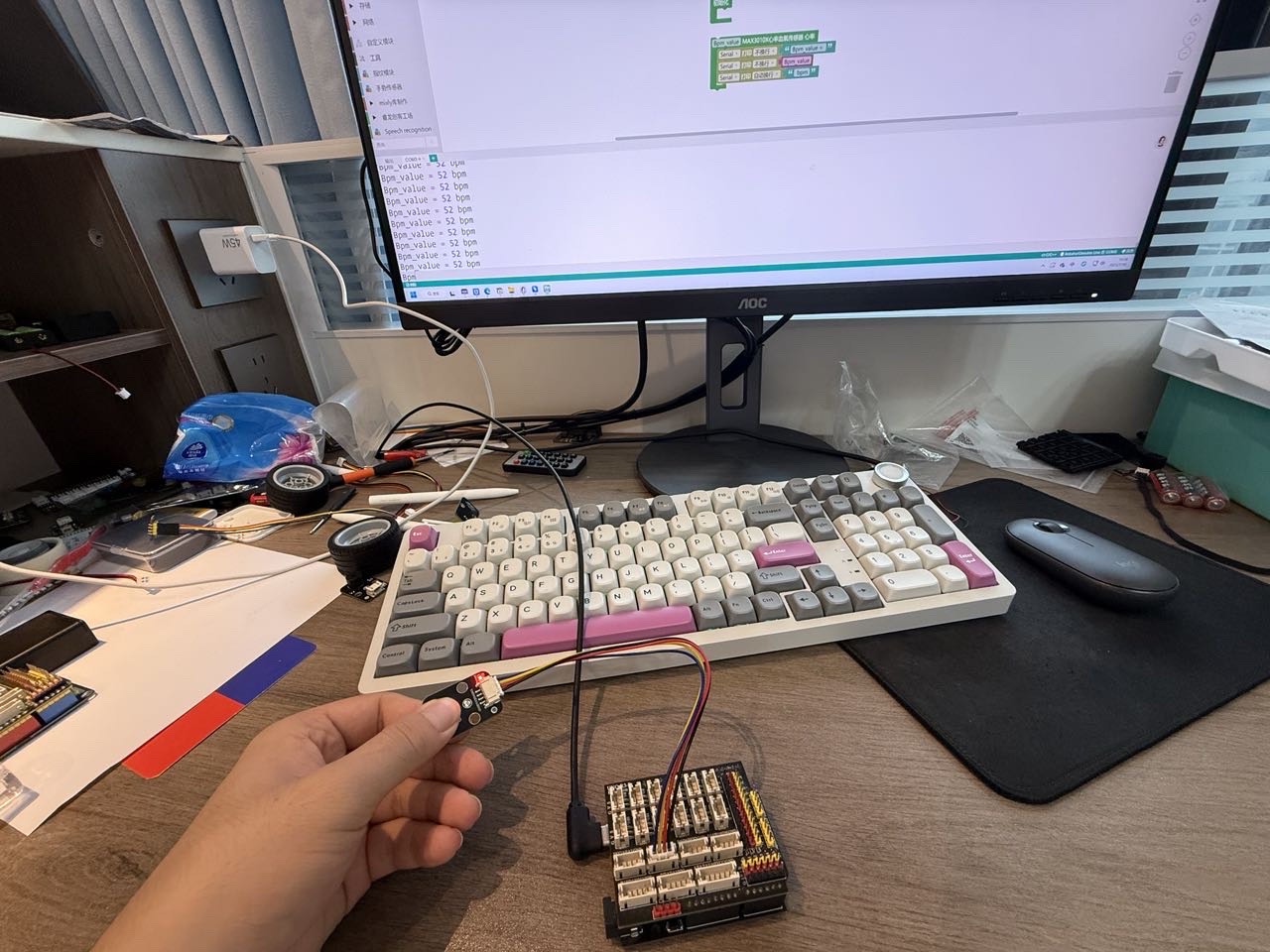
8、테스트 환경 구축
Arduino UNO 테스트 환경 구축
부품 준비:“
HELLO STEM UNO R3 개발 보드 *1
HELLO STEM UNO EXP1 확장보드 *1
USB type-c 데이터 케이블 *1
심장 박동 센서 모듈(HS-S70-P)*1
PH2.0 4P 케이블 *1
전기 연결도): 업데이트 중...
ESP32 테스트 환경 설정
부품 준비:“
ESP32EA MOC 개발 보드 *1
ESP32-EXP1 확장 보드 *1
USB type-c 데이터 케이블 *1
심장 박동 센서 모듈(HS-S70-P)*1
PH2.0 4P 케이블 *1
전기 연결도): 업데이트 중...
9、비디오 강의
비디오 강의:点击查看
10、테스트 결과
Arduino UNO 테스트 결과:
업데이트 중...
ESP32 테스트 결과:
장치를 연결하고 라인을 끊은 후, 위의 프로그램을 개발 보드에 업로드하면 심장 박동 센서 모듈 데이터 테스트를 볼 수 있습니다.