
1、소개
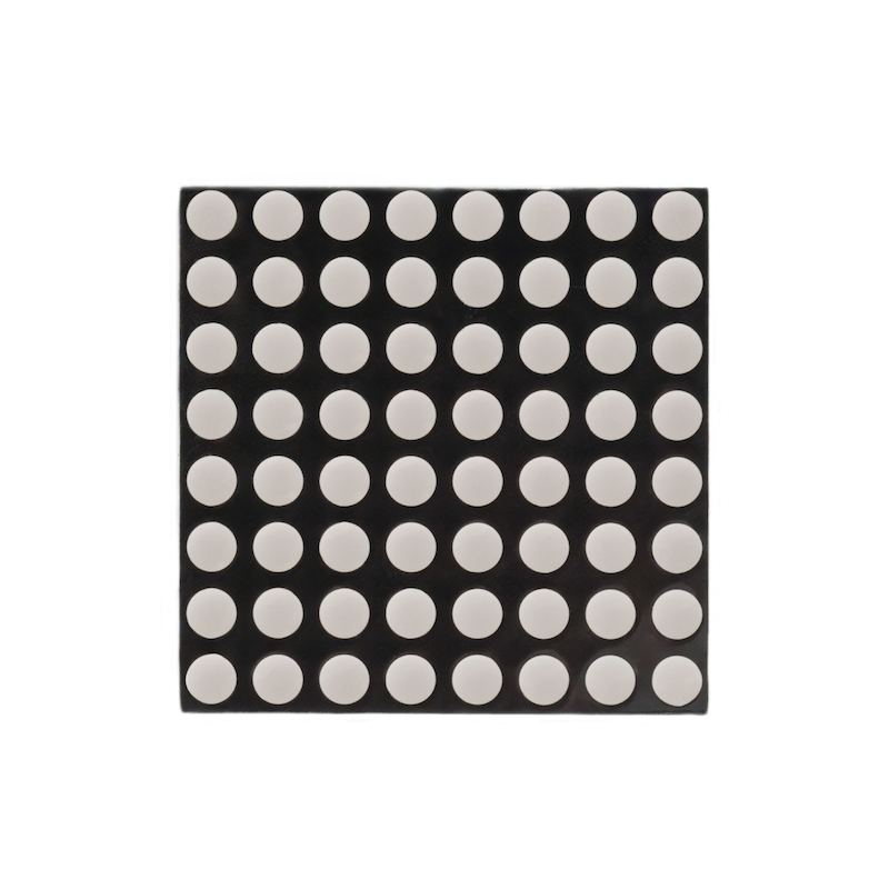
8*8 점陣 모듈은 MAX7219으로 구동되며, MAX7219은 통합된 시리얼 입력/출력 디스플레이 드라이버입니다. 3개의 IO 포트만으로 1개의 점陣을 구동할 수 있으며, 점陣 디스플레이는 깜빡이지 않으며 캐시드 지원을 합니다.8*8 점陣 모듈은 Max7219 드라이버를 통해 제어되며, Max7219은 세선 시리얼 통신을 사용합니다. Arduino 데이터를 수신할 때는 칩 내부 8*8 비트 스태틱 RAM에 데이터를 저장하고, 8*8 점陣 모듈의 각 핀의 고저전압 저전압을 통해 Max7219을 통해 8*8 점陣 모듈을 제어하여 표시 목적을 달성합니다.
2、시뮬레이션 그래프
8X8DotMatrixDisplay-HS-F13A원리도点击查看
3、모듈 매개변수
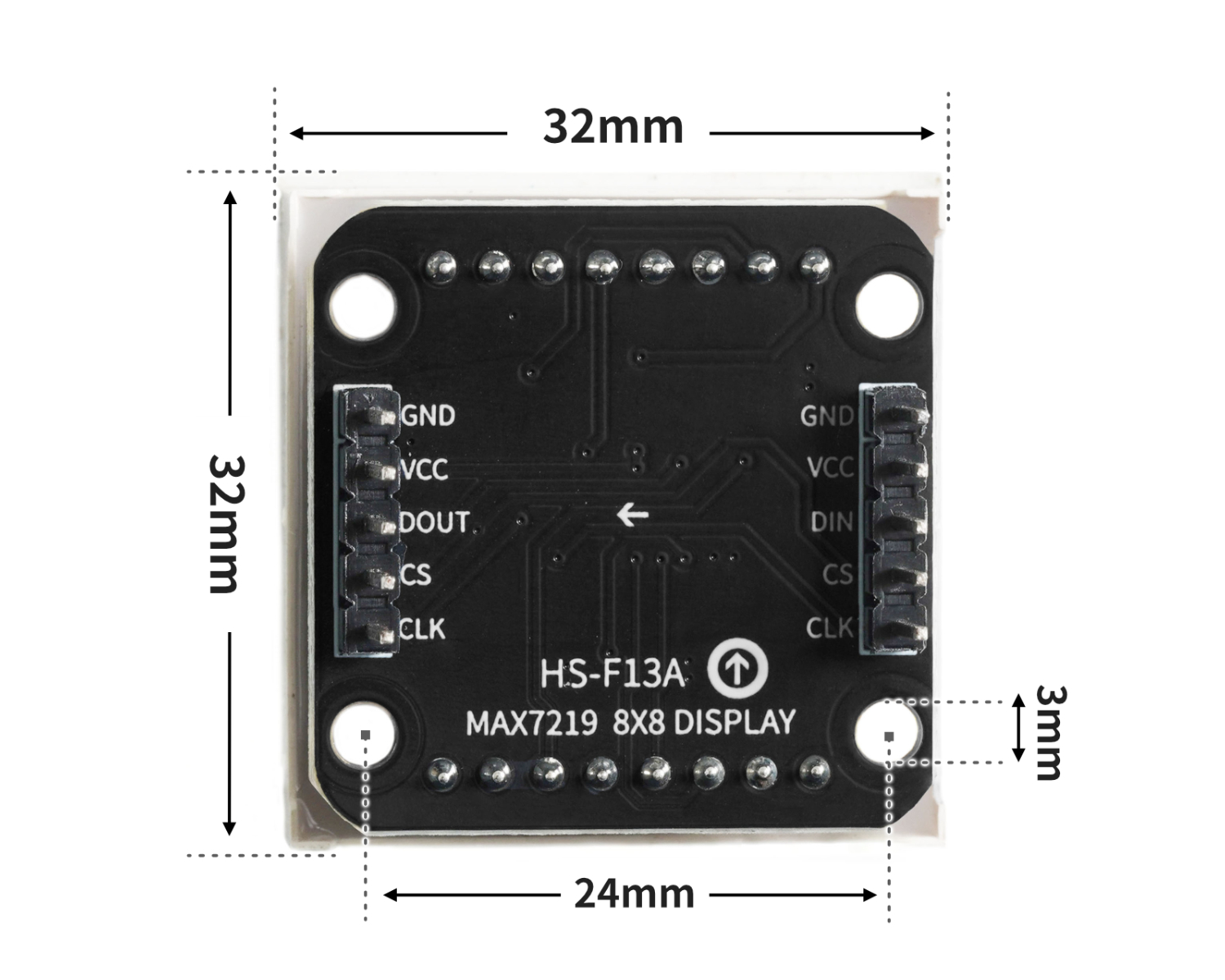
핀 이름 | 설명 |
|---|---|
CLK | 시계핀 |
CS | 셀렉트 레지스터 핀 |
DIN | 데이터핀 |
VCC | VCC(전원 입력 정극) |
GND | GND(전원 입력 부정极” |
전원전압: 3.3V / 5V
연결 방식: 2.54mm 레이아웃 핀저
설치방식: 더블스크루 고정
4、회로판 크기
5、아두이노 IDE 예제 프로그램
주의: 프로그램을 업로드할 때 라이브러리 파일 오류가 표시되면 먼저 라이브러리 파일을 가져오세요!
Arduino IDE 라이브러리 다운로드 및 导入 가이드:点击查看
예제 프로그램(UNO 개발 보드):
#include <SPI.h>
#include <Adafruit_GFX.h>
#include <Max72xxPanel.h>
Max72xxPanel myMatrix = Max72xxPanel(9,1,1);
uint8_t LEDArray[8];
const uint8_t LedArray1[8] PROGMEM ={0x00,0x18,0x24,0x00,0x00,0xa5,0x42,0x00};
const uint8_t LedArray2[8] PROGMEM ={0x00,0x24,0x18,0x00,0x00,0x24,0xc3,0x00};
void setup(){
myMatrix.setRotation(0,3);
myMatrix.fillScreen(0);
myMatrix.write();
}
void loop(){
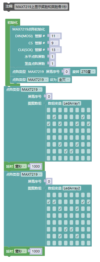
//MAX7219上显示笑脸和哭脸各1秒
memcpy_P(&LEDArray, &LedArray1, 8);
for(int index_i=0; index_i<8; index_i++)
{
for(int index_j=0*8; index_j<0*8+8; index_j++)
{
if((LEDArray[index_i]&0x01)>0)
myMatrix.drawPixel(index_j, 7-index_i,1);
else
myMatrix.drawPixel(index_j, 7-index_i,0);
LEDArray[index_i] = LEDArray[index_i]>>1;
}
}
myMatrix.write();
delay(1000);
memcpy_P(&LEDArray, &LedArray2, 8);
for(int index_i=0; index_i<8; index_i++)
{
for(int index_j=0*8; index_j<0*8+8; index_j++)
{
if((LEDArray[index_i]&0x01)>0)
myMatrix.drawPixel(index_j, 7-index_i,1);
else
myMatrix.drawPixel(index_j, 7-index_i,0);
LEDArray[index_i] = LEDArray[index_i]>>1;
}
}
myMatrix.write();
delay(1000);
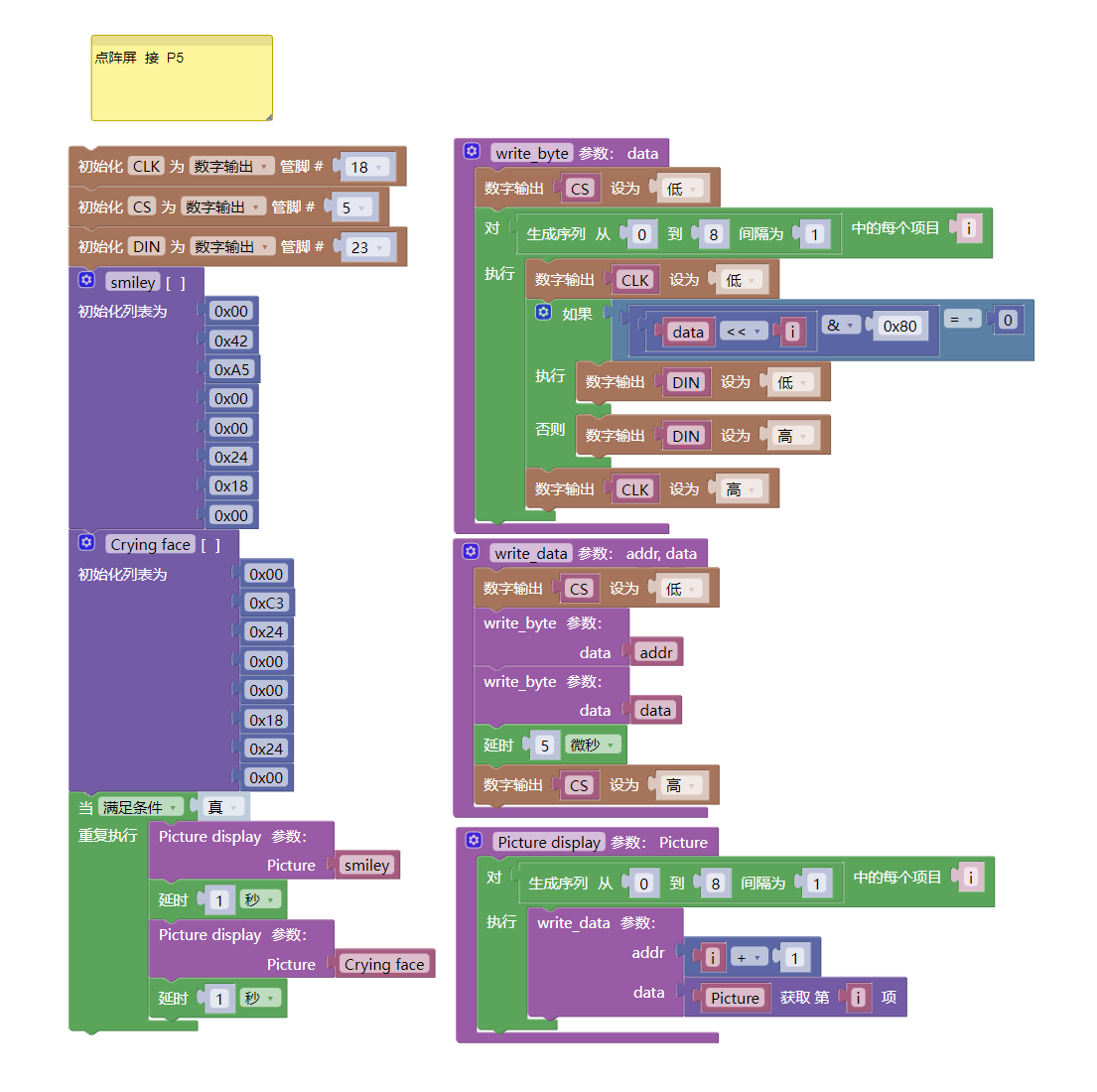
}6、ESP32 Python 예제(Mixly IDE /미스키에 적용됨)
개발 보드를 선택하세요 Python ESP32 【ESP32 Generic(4MB)】를 코드 모드로 전환하여 업로드하십시오
주의: 프로그램을 업로드할 때 라이브러리 파일 오류가 표시되면 먼저 라이브러리 파일을 가져오세요!
미시지(Mixly)IDE ESP32 라이브러리 다운로드 및 가져오기 가이드:点击查看
예제 프로그램(ESP32-Python):
import machine
import time

def write_byte(data):
    CS.value(0)
    for i in range(0, 8, 1):
        CLK.value(0)
        if ((data<<i)&0x80) == 0:
            DIN.value(0)
        else:
            DIN.value(1)
        CLK.value(1)

def write_data(addr, data):
    CS.value(0)
    write_byte(addr)
    write_byte(data)
    time.sleep_us(5)
    CS.value(1)

def Picture_display(Picture):
    for i in range(0, 8, 1):
        write_data(i + 1, Picture[i])


CLK = machine.Pin(18, machine.Pin.OUT)
CS = machine.Pin(5, machine.Pin.OUT)
DIN = machine.Pin(23, machine.Pin.OUT)
smiley = [0x00, 0x42, 0xA5, 0x00, 0x00, 0x24, 0x18, 0x00]
Crying_face = [0x00, 0xC3, 0x24, 0x00, 0x00, 0x18, 0x24, 0x00]
while True:
    Picture_display(smiley)
    time.sleep(1)
    Picture_display(Crying_face)
    time.sleep(1)
7、미스키 Mixly 예제 프로그램(그래픽 언어)
예제 프로그램(UNO 개발 보드):다운로드 클릭
주의: 프로그램을 업로드할 때 라이브러리 파일 오류가 표시되면 먼저 라이브러리 파일을 가져오세요!
미스키(Mixly)IDE Arduino 라이브러리 다운로드 및 가져오기 가이드:点击查看
예제 프로그램(ESP32 개발 보드):다운로드 클릭
주의: 프로그램을 업로드할 때 라이브러리 파일 오류가 표시되면 먼저 라이브러리 파일을 가져오세요!
미시지(Mixly)IDE ESP32 라이브러리 다운로드 및 가져오기 가이드:点击查看
8、테스트 환경 구축
Arduino UNO 테스트 환경 구축
부품 준비:“
HELLO STEM UNO R3 PRO 개발보드 *1
HELLO STEM UNO R3 P확장판 *1
USB type-c 데이터 케이블 *1
8X8점阵 디스플레이(HS-F13A)*1
PH2.0 5P 케이블 전환선*1
전기 연결도):
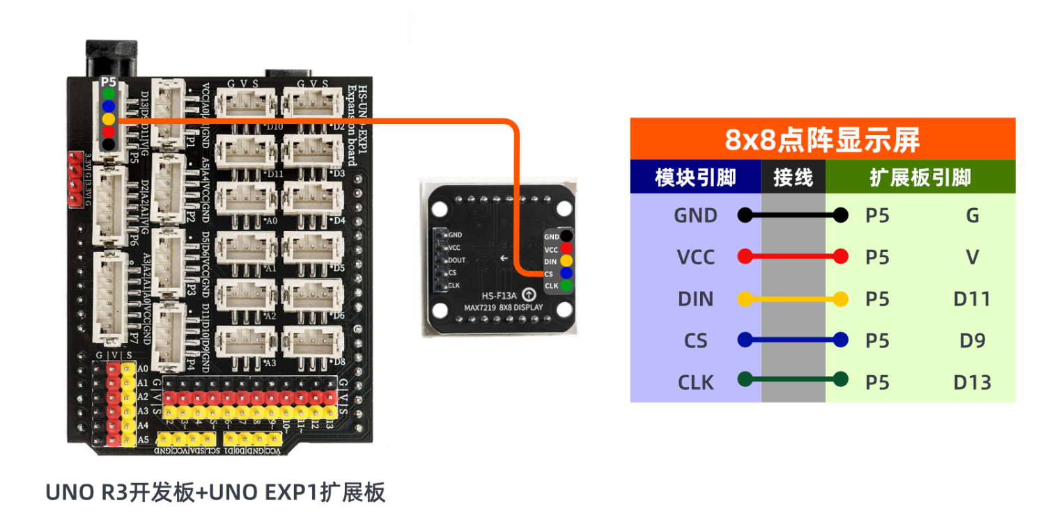
ESP32 테스트 환경 설정
부품 준비:“
ESP32EA MOC 개발 보드 *1
ESP32-EXP1 확장 보드 *1
USB type-c 데이터 케이블 *1
8X8점阵 디스플레이(HS-F13A)*1
PH2.0 5P 케이블 전환선*1
전기 연결도): 업데이트 대기 중...
9、비디오 강의
비디오 강의:点击查看
10、테스트 결과
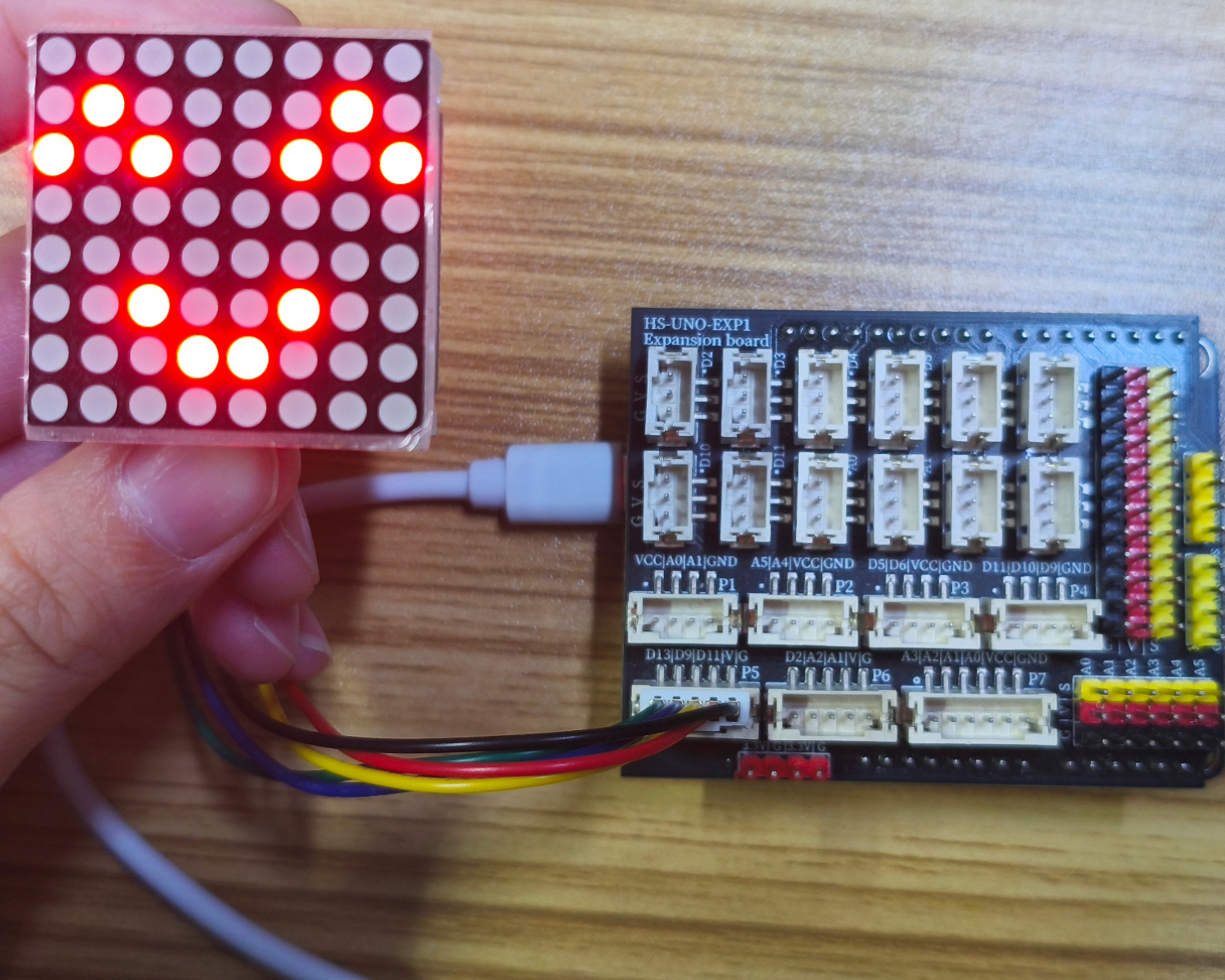
Arduino UNO 테스트 결과:
선을 연결한 장치에 대해, 위의 프로그램을 개발 보드에 기록한 후, 리셋 키를 누르면 미소와 우울한 얼굴이 순환으로 표시됩니다。
ESP32 테스트 결과:
업데이트 대기 중...